Program memory modules / Interface modules
8-12 Hardware - SIMADYN D
Edition 04.2011
Voltages 1P and 1M can be used, via the double test socket (G; +) to
simulate an input signal for SIMADYN D.
Double test socket X5 Voltage
+ (1P from X3)
G (1M from X3)
+24 V
0 V
!
WARNUNG Explosion Hazard
No connections are to be made to X5 unless the area is known to be
non-hazardous.
8.4.1 Signals
Each status of the 8 signals is displayed using a yellow LED (1...8).
There is a screw connection for each signal at the two terminal strips X2:
• terminals 1 to 8 for binary signals
• terminals 51 to 58 for reference points
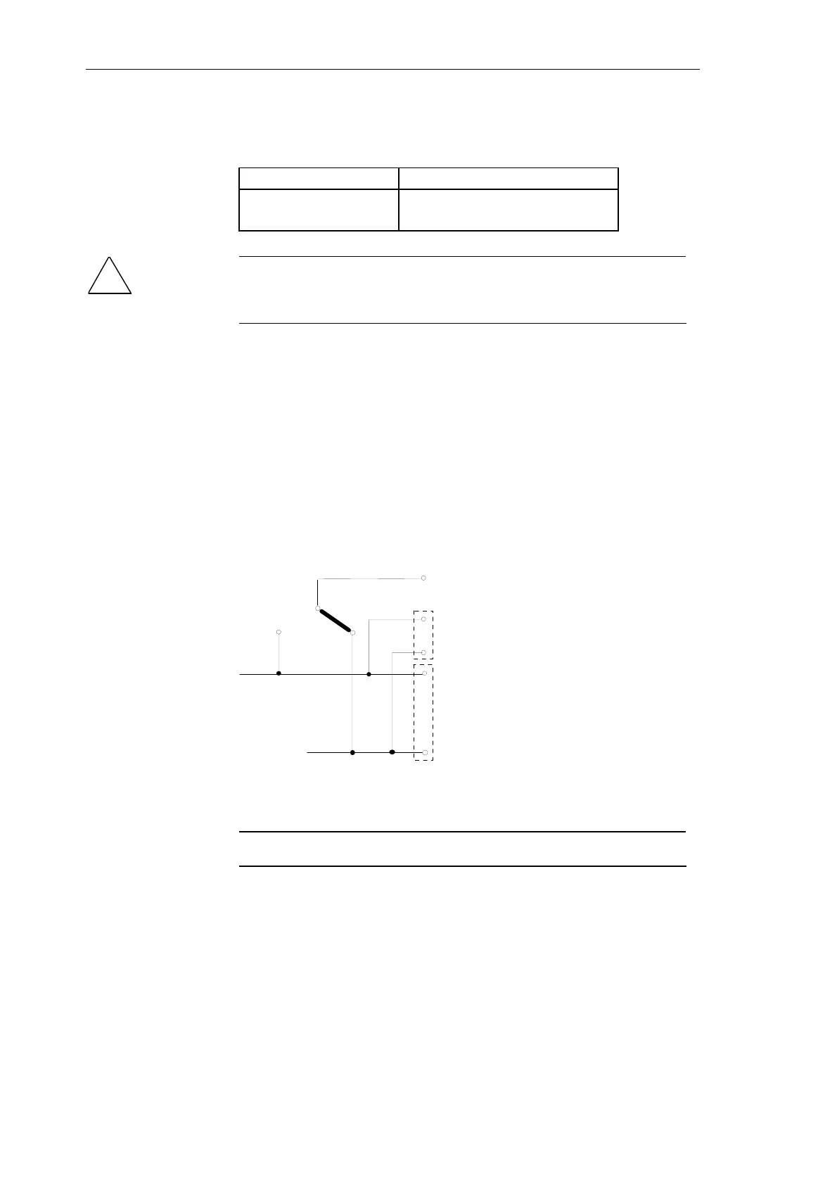
The reference points of the signals are either at 1M potential or 1P
potential. The polarity is selected on the module using a solder link:
X2
51..58
X5
1P
1W
1M
X3
1P
1M
G
+
Fig. 8-5 Solder link to set the signal reference points
NOTE
Link 1M-1W is inserted in the factory
Test socket
Yellow LED
Reference potential
of the signals

 Loading...


