Program memory modules / Interface modules
Hardware - SIMADYN D 8-15
Edition 04.2011
8
8.4.4 Connector assignment
To connect the interface module to the SIMADYN D / SIMATIC TDC /
S7-400 FM 458- components use cable SC62 or SC64 (for further
informations see the documentation of the SIMADYN D / SIMATIC TDC /
S7-400 FM 458- components).
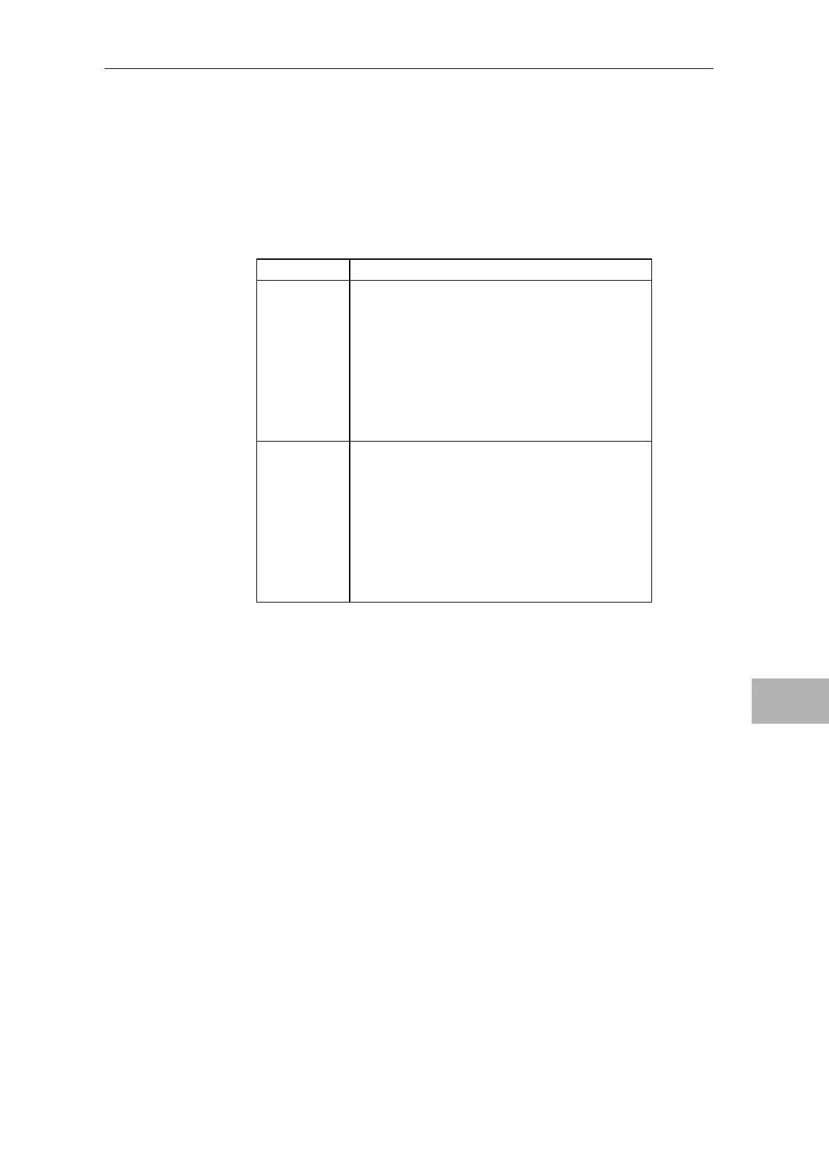
Terminal Designation
1
2
3
4
5
6
7
8
Channel 1 (binary input/output 1)
Channel 2 (binary input/output 2)
Channel 3 (binary input/output 3)
Channel 4 (binary input/output 4)
Channel 5 (binary input/output 5)
Channel 6 (binary input/output 6)
Channel 7 (binary input/output 7)
Channel 8 (binary input/output 8)
51
52
53
54
55
56
57
58
Reference rail, 1M (1P can be set)
Reference rail, 1M (1P can be set)
Reference rail, 1M (1P can be set)
Reference rail, 1M (1P can be set)
Reference rail, 1M (1P can be set)
Reference rail, 1M (1P can be set)
Reference rail, 1M (1P can be set)
Reference rail, 1M (1P can be set)
Table 8-4 Assignment of the binary inputs and outputs of interface module SB10
The minimun conductor cross section for the terminal block X2 is
0,2mm², the maximum conductor cross section is 2,5 mm².
Flat connector X1
Terminal block X2
Conductor cross
section

 Loading...


