Input/output modules
Hardware - SIMADYN D 5-49
Edition 12.2004
5
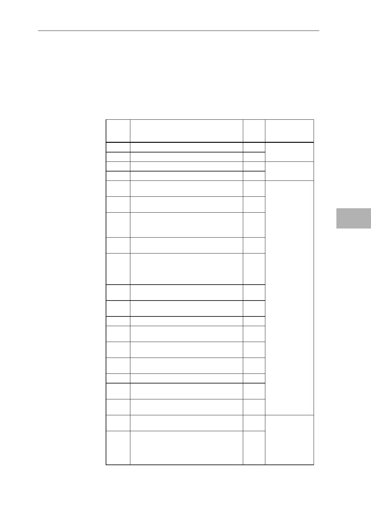
5.5.2 Connector assignment X5
Connector X5 (20-pin plug connector) connects signals for
• 2 analog outputs
• SITOR start-up signals
The SU11 interface module can be connected via SC12 plug-in cable (1:1-
connection from the module to the terminals):
ITDC
X5 Pin
Designation SU 11
X2
Connector
designation for
configuring
1 Analog output 1+ 1 X5A
2 Ground, analog output 1 2
3 Analog output 2+ 3 X5B
4 Ground, analog output 2 4
5 External synchronizing voltage, L1 for 3-
phase synchronization
5
6 Reference voltage for the synchronizing
voltage
6
7 P15 output, 15V
(R
i
=600 ohm, not suitable to supply the
encoders)
7
8 Measuring signal "Zero crossover of the
SITOR power supply phase voltage" L13
8
9 Display, zero crossover signal identification,
synchronizing voltage
Logic signal level 15V, Ri=2.2K ohm for an
"H" signal
9
10 External pulse inhibit, if connected to pin 7
or 24V -> pulses enabled
10
11 Excitation current setpoint, 0..10V, R
i
=2.2K
ohm
11
12 Measuring signal "Summed pulses" 12
13 Analog current actual value +/-10V,
R
i
=2.2K ohm
13
14 Ground (digital), reference potential for
measuring signals
14
15 Measuring signal, "Total pulse inhibit",
pulses enabled = 5V
15
16 Ground, synchronizing module 16
17 Synchronizing voltage U12 for 3-phase
synchronization
17
18 Synchronizing voltage U23 for 3-phase
synchronization
18
19 Synchronizing voltage U31 for 3-phase
synchronization
19
20 Pulse chain synchronizing, connected with
additional PG11/PG16 or ITDC
"H" output voltage: 10-14V
"H" output current: 40mA
20
Table 5-40 Pin assignment ITDC, connector X5 and terminal assignment SU11,
SU11 analog
outputs and start-
up signals via the
SC12 cable

 Loading...


