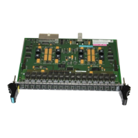
Input/output modules
5-50 Hardware - SIMADYN D
Edition 12.2004
5.5.3 Connector assignment X6
Connector X6 (20-pin plug connector) connects the signals for:
• 4 binary inputs
• 4 binary outputs
• 1 speed input
The SU11 interface module can be connected via the SC12 plug-in cable
(1:1 connection from the module to the terminals):
ITDC
X6 Pin
Designation SU 11
X2
Connector
designation
for
configuring
1 Binary input 1
1 X6A
2 Binary input
2
2
3 Binary input
3
3
4 Binary input
4
4
5 Binary output 1 5 X6G
6 Binary output 2 6
7 Binary output 3 7
8 Binary output 4 8
9 P
ext
, positive power supply, max. 30 V 9
10 M
ext
, 0V power supply 10
11 Speed sensing, track 1A- 11 X6C
12 Speed sensing, track 1A+ 12
13 Speed sensing, track 1B- 13
14 Speed sensing, track 1B+ 14
15 Speed sensing, zero pulse 1N- 15
16 Speed sensing, zero pulse 1N+ 16
17 Coarse pulse 17
18 GND ext. 18
19 GND ext. 19
20 n. c. 20
Table 5-41 Pin assignment ITDC, connector X6 and terminal assignment SU11
5.5.4 Connector assignment X7
Connector X7 (sub-D 50-pin) connects the signals to control (gate) a SITOR
set (three-phase bridge).
Via plug-in cable:
• SC17.2 (screened round cable, 50-pin SUB-D, 2m long), or
• SC31.2 (screened round cable, 50-pin SUB-D, 10m long)
The module can be directly connected to a SITOR set.
SU11 binary
input/output and
speed sensing via
cable SC12

 Loading...


