Input/output modules
5-4 Hardware - SIMADYN D
Edition 12.2004
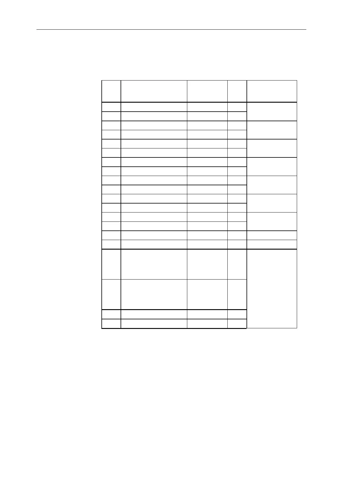
5.1.2 Connector assignment X5
EA12
X5
Significance Associated
test socket
SU11
Connector
designation when
configuring
1 Analog output 1 X11 SIG 1 X5A
2 Ground X11 COM 2
3 Analog output 2 X12 SIG 3 X5B
4 Ground X12 COM 4
5 Analog output 3 X13 SIG 5 X5C
6 Ground X13 COM 6
7 Analog output 4 X14 SIG 7 X5D
8 Ground X14 COM 8
9 Analog output 5 X15 SIG 9 X5E
10 Ground X15 COM 10
11 Analog output 6 X16 SIG 11 X5F
12 Ground X16 COM 12
13 Analog output 7 X17 SIG 13 X5G
14 Ground X17 COM 14
15 Analog output 8 X18 SIG 15 X5H
16 Ground X18 COM 16
17 Electronics ground
(connected with the
electronics ground via 0
Ohm resistor)
--- 17
18 Electronics ground
(connected with the
electronics ground via 0
Ohm resistor)
--- 18
19 Ground --- 19
20 Ground --- 20
Table 5-3 EA12 connector- and SU11 terminal assignment
All of the "ground" terminals are connected together via 0 Ohm resistors
and are connected to electronics ground via an associated inductance.
5.1.3 Application information and noise immunity
• operation without fan is possible
• noise-immune operation is only possible if the module is tightly screwed
into the subrack
The input/output signals must be screened on the plant/system side. The
screen must be connected through the largest possible surface area to the
screen rail between the interface module and where the cable enters or exits
the cabinet.
SU11 terminal
assignment
Screening

 Loading...


