Communications support modules
Hardware - SIMADYN D 6-43
Edition 12.2004
6
We are preparing an Internet page for SIMADYN D.
6.9.2 Mounting guidelines and noise immunity
The front panel of the communications module must be connected to the
front panel of the CS7 using the cables provided with the CS7.
The screen of the data transfer cable (bus cable) must be grounded to a
grounding rail through the largest possible surface area where the cable
enters the equipment.
In addition, the screen in the connector housing must be connected to the
housing. The connector must be tightly screwed to the communications
module.
Further information on EMC and ambient conditions, refer to Section
„General technical data“
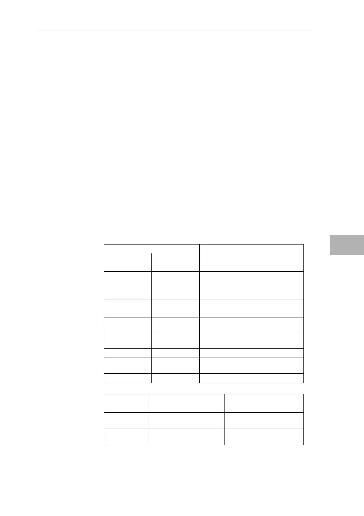
6.9.3 Diagnostics LED
Each receptacle of the CS7 support module has 2 LEDs, which allow
diagnostics of the associated communications module (operating- and
error/fault conditions).
LEDs on CS7 Significance for SS5
Green
H10 / H20 / H30
Yellow
H11 / H21 / H31
Dark Dark Processor not initialized
Dark Lit Without database at the bus;
COMSS5 must be parameterized
Dark Flickers No database, with bus activity;
COMSS5 must be parameterized
Slow
flash
Dark Initialization erroneous;
COMSS5 database erroneous
Fast
flash
Dark Initialization phase 1
Lit Dark Initialization phase 2
Lit Lit Correctly connected at the bus; presently
no bus activity
Lit Flickers Bus activity
LED Green
H10 / H20 / H30
Yellow
H11 / H21 / H31
Dark CPU stopped No bus operation (initialization
phase)
Flashing, 5 Hz Fatal error:
Read-out the error codes at
Error on the bus,
e. g. short-circuit:
Grounding the
front panel with
CS7
Cable
screening
Other information
CS7 LED for SS5
CS7 LED for SS52

 Loading...


