Operator control panel OP2
10-18 Hardware - SIMADYN D
Edition 03.2001
10.5 System run-up
OP2 is powered-up by switching-on the +24V power supply voltage. All of
the connections must be correct to ensure perfect functioning of the unit:
• USS connecting cable to SIMADYN D
• printer cable (if a printer is connected).
• power supply cable
After being powered-up, the „
OP2 Version V1.0“ message is displayed for
approximately 5 seconds (the actual firmware version is displayed).
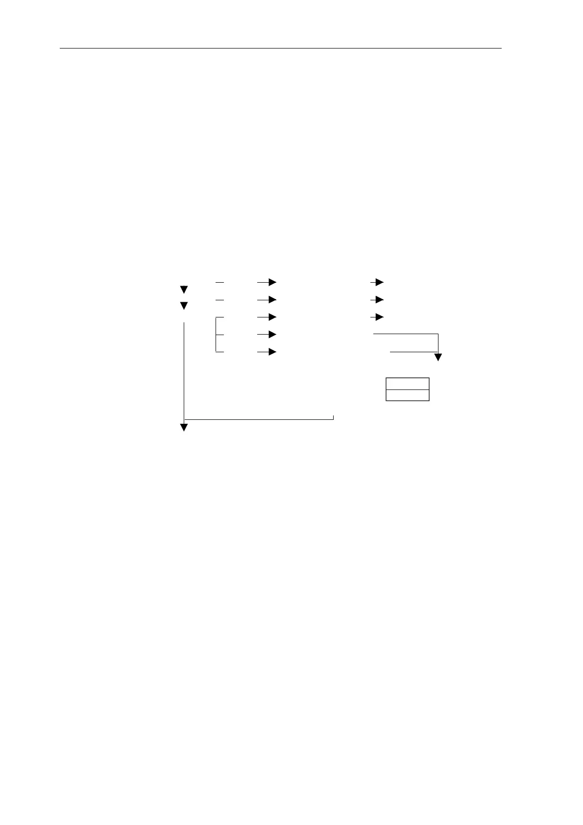
OP2 then goes into an automatic hardware test routine. The following
messages occur one after the another during this test routine:
EPROM ok Error EPROM -memory failure (OP2 defect/replace)
RAM ok Error RAM-memory failure (OP2 defect/replace)
FLASH-TEST Error FLASH-memory failure (OP2 defect/replace)
Error FLASH-memory erased
Error FLASH-memory chsum wrong
- incorrect contents/checksum of the FLASH memory
- FLASH is re-initialized
- run-up with DEFAULT initialization
TEST ok
FLASH-TEST
- - -
The OP2 then automatically establishes a communications link to SIMADYN
D.
10.5.1 Establishing a communications link to SIMADYN D
After a successful self-test, OP2 establishes a communications link to the
SIMADYN D subracks.
This procedure can either be initiated by SIMADYN D or by the OP2. This is
realized as follows
• SIMADYN D: After resetting or powering-up the subrack power supply.
• OP2: After powering-up the OP2 power supply voltage or, optionally,
when exiting the SYSTEM mode (for menu item „INIT REQUEST“ in the
main menu „END“).
When OP2 starts to establish the link, the following message is displayed
„INITIALIZATION REQUESTED“ (upper display line). After the first data
have been exchanged with SIMADYN D, the process values are
automatically initialized (message in the lower display line: „PROCESS
DATA INITIALIZATION“) and then the binary value initialization (message in
the lower display line: „BINARY VALUE INITIALIZATION“).
Power-on
Hardware test
Establishing the
communications
link

 Loading...


