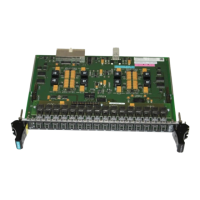
Input/output modules
5-2 Hardware - SIMADYN D
Edition 12.2004
5.1 Input/output modules EA12
6DD1642-0BC0
• 8 analog outputs
• 20-pin connector for the analog outputs
• 8 test socket pairs (2.3 mm) on the front panel to connect measuring
equipment (for start-up)
• L bus connection
An analog output (signal at the connector and interface module and at the
test socket) can be loaded up to 10 mA and is short-circuit proof for 2 min.
The manufacturer adjusts the outputs as far as offset and gain are
concerned for an ambient temperature of approximately 20° C:
This adjustment is made using 2 potentiometers for each output, which are
not sealed so that they can be re-adjusted in operation (e. g. due to different
ambient temperatures).
The temperature dependency is max. approx. +/-240 µV at a temperature
change of +/-1° C.
Analog output Offset Gain
Output 1 -R49 -R46
Output 2 -R55 -R52
Output 3 -R61 -R58
Output 4 -R67 -R64
Output 5 -R73 -R70
Output 6 -R79 -R76
Output 7 -R85 -R82
Output 8 -R91 -R88
Table 5-1 Adjustment potentiometers for analog outputs
The module should be operated for approx. 2 min before any adjustment is
made so that it has time to reach its operating temperature.
The offset adjustment is first made. The value 0.0 (0%) should be output in
the configured software at the connection of the associated function block,
and the associated offset potentiometer should be adjusted until 0 V is
measured.
The output voltage is increased by rotating the potentiometer clockwise.
The gain is then adjusted. The associated analog output should be driven
with 2.0 (200%) (configured software) and the associated offset
potentiometer should be adjusted until 10 V is measured.
The switch-mode power supply causes voltage spikes (these can be
measured up to 100 mV) on the ground cable. They can be suppressed by:
• smoothing at the load input
• low-ohmic load
5.1.1 Supplementary components
All of the cables for the output signals are not directly connected at the
module, but via interface modules. The interface modules serve as
mechanical connecting element (screw/plug-in terminals) and toelectrically
adapt the system/plant signals (optional).
Order No.
Features
Load capability
Adjustment,
temperature
Adjustment
Noise signals at
the outputs
Interface modules
with terminals

 Loading...


