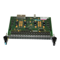
Technology subrack
Hardware - SIMADYN D 7-3
Edition 03.2001
7
• 2 analog outputs
• 5 analog inputs
• 2 binary outputs
• 4 bi-directional binary inputs/outputs
• 8 binary inputs, of which a maximum of 4 can be used to call-up interrupt
tasks
• 2 incremental encoder connections with zero pulse
• 2 coarse pulse connections to suppress zero pulses;
rough pulses can be optionally used as binary input
• 2 absolute value encoder connections (SSI/EnDat interface);
absolute value encoder connection 2, optionally to serial interface 2!
• Serial interface 1 for
− download and service with DUST1 protocol(RS 232) or
− USS protocol (RS 485)
• Serial interface 2 (RS 485), optionally to absolute value encoder
connection 2 for
USS (master or slave) or peer-to-peer
• The module is configured by downloading data into the permanently
inserted flash EPROM (the EPROM is soldered-in)
• MASTER DRIVES operator control panel OP1S and SIMOVIS can be
connected via USS slave for parameterization (for applications without
MASTER DRIVES BASE-BOARD (CU), e. g. in the SRT400)
• 2*T400 can be used in the SRT400 subrack
• Selectable T400 synchronizing from the BASE- or COM BOARD,
synchronizing signals can be output to the BASE- and COM BOARD;
• Dual port RAM interface to MASTER DRIVES
BASE BOARD, CU and
interface to the dual port RAM on a communications module (COM
BOARD CB)
• 32-bit RISC processor, 32 MHz
• 2Mbyte Flash for compressed program code.
• 4Mbyte DRAM for the de-compressed (unzipped) program which can be
run
• 32 kbyte permanent change memory (EEPROM)
(e.g. for fuzzy control)
• 4 kbyte dual port RAM
Inputs/outputs
Functional features
Features,
electronics

 Loading...


