Technology subrack
7-6 Hardware - SIMADYN D
Edition 03.2001
• TTL (0V ... 5V)
The setting is made using the DIL switches S2/1 - S2/8
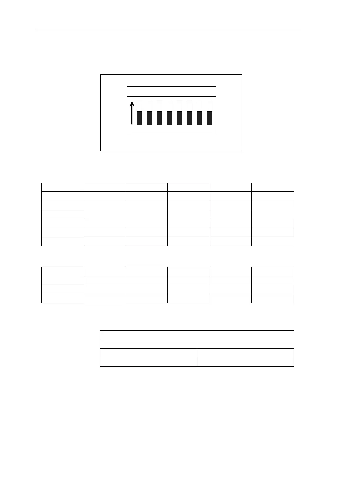
ON
23456781
Fig. 7-2 Switch S2
Track signals A and B are set according to the following table:
Significance Switch S2 Setting Significance Switch S2 Setting
TTL RS422 1 ON TTL (0V ... 5V) 1 ON
2 ON 2 ON
3 ON 3 OFF
HTL± (±3V) 1 OFF HTL (3V ... 8V) 1 OFF
2 OFF 2 OFF
3 OFF 3 OFF
The zero impulse can be switched indepenent from Track A or B:
TTL RS422 4 ON TTL (0V ... 5V) 4 ON
5 ON 5 OFF
HTL± (±3V) 4 OFF HTL (3V ...8V) 1 OFF
5 ON 2 OFF
For differential signals, bus terminating resistors can be switched-in via
switch S2/6 - 8:
Significance Switch S2
Track A 6
Track B 7
Zero pulse 8
The terminating resistors are switched-out in the OFF setting; they are
switched-in in the ON setting.
The switches can only be changed when the module has been withdrawn.
The switches are not accessible when the module is inserted.

 Loading...


