Operator control panel OP2
10-28 Hardware - SIMADYN D
Edition 03.2001
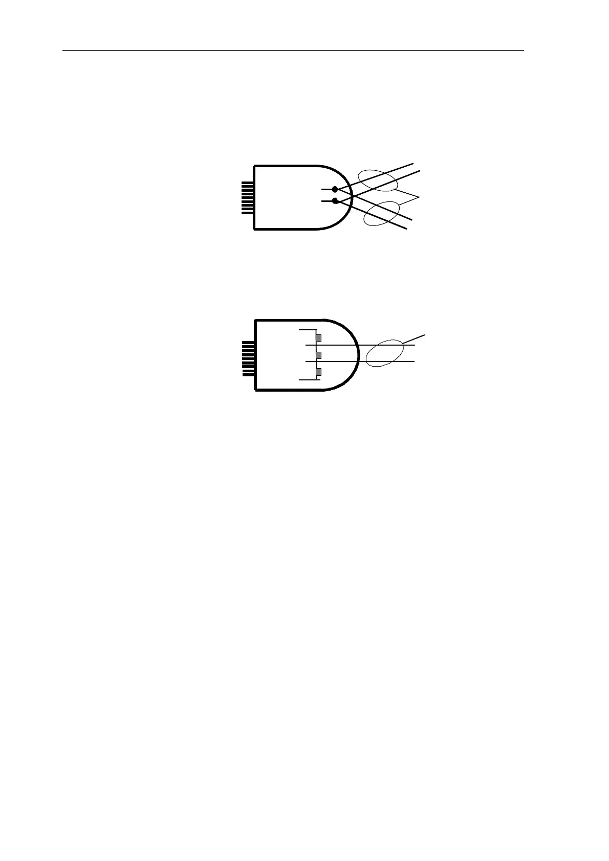
The connection is realized via a 9-pin sub-D connector with the following
circuit configuration:
A) Connection as a node (station) at the center of the BUS
DATA B
DATA A
B
A
B
A
(3)
(8)
BUS cable
9-pin sub-D
B) Connected as node at the end of the BUS (with bus termination
):
P
N
BUS-Kabel
9
-
polig Sub-D
150
Ω
390
Ω
390
Ω
(6)
(3)
(8)
(5)
+5 V
Data B
Data A
End
A bus terminating resistor network must be installed in connector 4 (refer
to the appropriate information specified with communications module SS4)
Bus connection
and cable

 Loading...


