Subracks
2-14 Hardware - SIMADYN D
Edition 04.2011
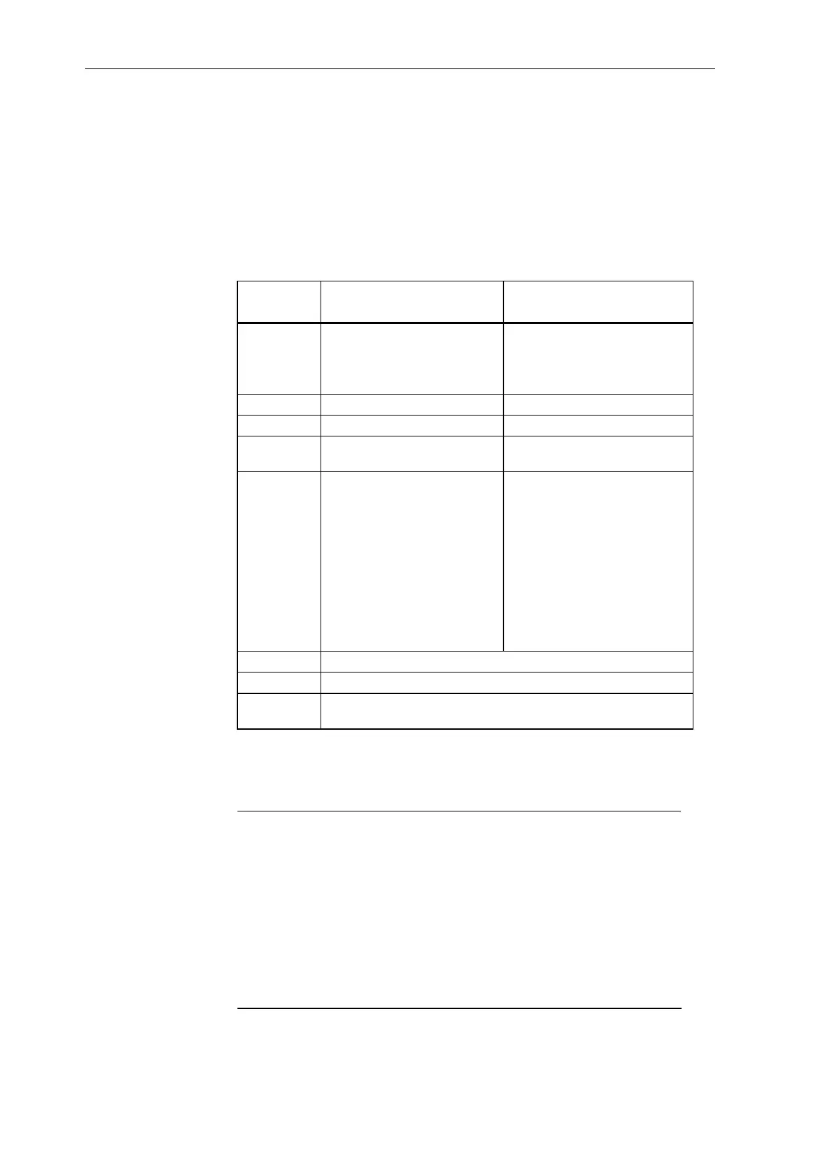
Test sockets to check the 3 output voltages 5 V, +/-15 V
(short-circuit proof)
The line supply voltage is connected through the 3-pole screw/plug-in
terminal X1.
The connection assignment is printed on the front panel:
Above the voltage selector switch (Slide switch) can be switched to between
an input nominal voltage from 230 V and 115 V.
The in each case valid value becomes visible with transfer of the switch.
SR12.1 and SR12.2
SR24.1 and SR24.2
SR12.3 and SR12.4
SR24.3 and SR24.4
Input voltage
24 V DC 230 V AC (default setting of
voltage selector switch )
115 V AC (change over voltage
selector switch )
X1 Pin 1 +24 V Phase conductor L
X1 Pin 2 Ground (0 V) Neutral conductor N
X1 Pin 3 Protective ground conductor
PE
Protective conductor PE
External fuse
(rating)
For SR12.x:
In = 16 A max..
I²t= 6 A²s
Is = 32 A
(inrush peak)
For SR24.x:
In = 32 A max..
I²t= 10 A²s
Is = 64 A
(inrush peak)
For SR12.x: (AC230V)
In = 1.2 A max..
I²t= 0.6 A²s
Is = 6 A
(inrush peak)
For SR24.x: (AC230V)
In = 2.7 A max..
I²t= 1 A²s
Is = 9 A
(inrush peak)
X2 pins 1 - 4 Monitoring the power supply and fan assembly (relay)
X3 pins 1 - 2 Feed for an external back-up battery
X4 pins 1 - 2 Reset: A reset is initiated by jumpering the contents (optional to
using the reset button)
The specified current In is the current that can occur at a maximum insertion
of the subrack. The power supplies are in part oversized, and have a higher
maximum input current (Chapter: Technical dates).
NOTES
The protective conductor must be connected at connector X1, pin 3.
It is not sufficient to connect a protective conductor at the subrack.
It must be a slightly accessible circuit breaker in the supply circuit.
Interface modules with binary output function SB70, SB71 should be
powered-up approximately 200 ms before the modules are powered-up
to prevent power-on effects.
This is achieved by simultaneously powering-up the subrack power
supplies (this requires approximately 200 ms to establish the voltages)
and the interface modules.
Supply connection

 Loading...


