Line Modules Booksize
3.4 Smart Line Modules (5 kW and 10 kW) with internal air cooling
Equipment Manuel for Booksize Power Modules
Manual, (GH2), Edition 06.2005, 6SL3097-2AC00-0BP2
3-49
3.4.3.4 X21 terminals: smart line module
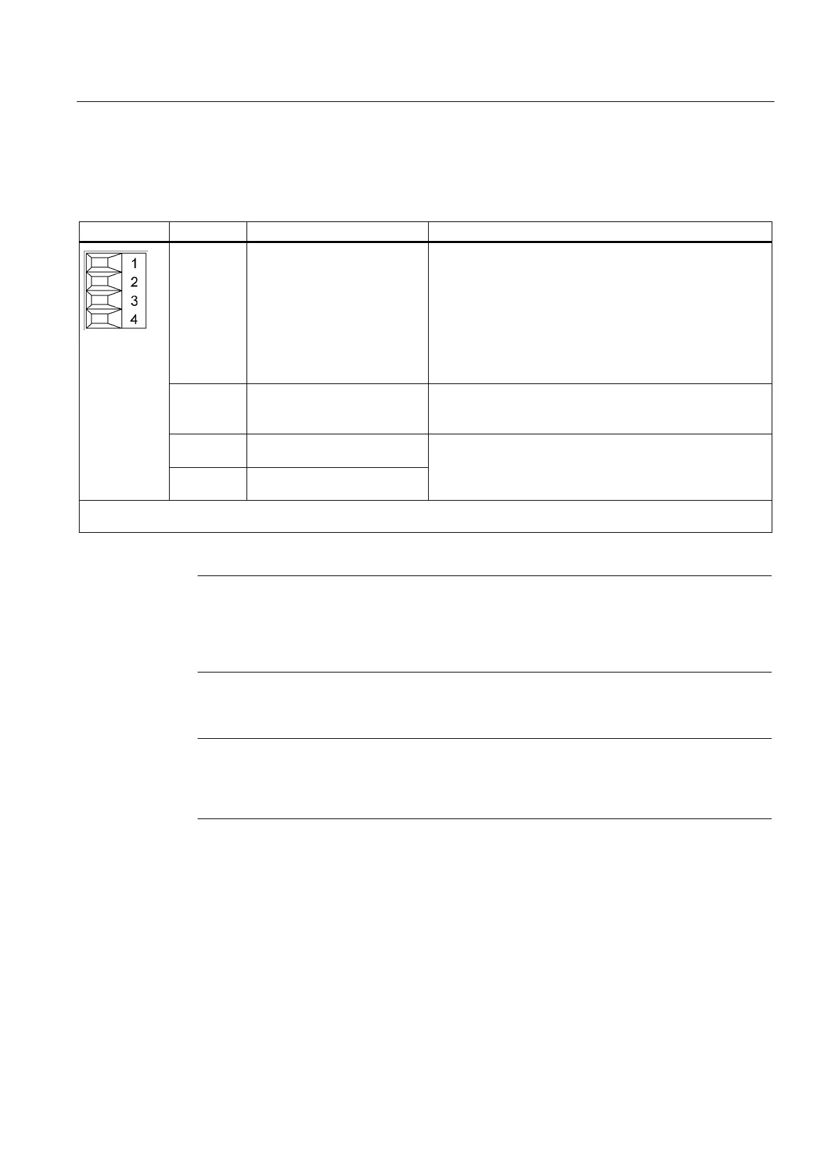
Table 3-22 Terminal block X21
Terminal Name Technical specifications
1 DO: Ready Checkback: Smart Line Module ready
The signal switches to high level when the following
conditions have been met:
• Electronics power supply (X24) OK
• DC link is pre-charged
• Pulses enabled (X21.3/.4)
• No overtemperature
• No overcurrent switch-off
2 DO: Pre Warning Prewarning threshold overtemperature / I x t
When 80% of the maximum temperature of the Smart Line
Module is exceeded, a high signal is output.
3 DI: Enable pulses
4 DI: Enable pulses ground
Voltage 24 V DC
Current consumption: 10 mA
Isolated input
Max. connectable cross-section: 1.5 mm
2
Type: Screw terminal 1 (see Spring-Loaded Terminals/Screw Terminals)
Note
For operation, 24 V DC must be connected to terminal 3 and ground to terminal 4. When
removed, pulse inhibit is activated, feedback is deactivated and the bypass relay drops out.
If the Line Module is not disconnected from the network when the EP terminal is deactivated
(e.g. a main contactor is not installed), the DC link remains charged.
Notice
If a drive line-up is switched off by means of the line disconnecting device, the voltage at
terminals 3 (EP +24 V) and 4 (EP M) must be interrupted beforehand. This can be carried
out using a leading breaking auxiliary contact (≥ 10 ms), for example.

 Loading...


