DC link components Booksize
5.5 Voltage Clamping Module (VCM)
Equipment Manuel for Booksize Power Modules
Manual, (GH2), Edition 06.2005, 6SL3097-2AC00-0BP2
5-29
5.5.5 Installation
See the instructions for installing other DC link components (e.g. Braking Module, Capacitor
Module).
Arrangement of the Voltage Clamping Module:
The Voltage Clamping Module should ideally be placed directly next to the Line Module.
• For Line Modules up to and including 36 kW, it should be placed to the right of the Line
Module.
• For Active Line Modules as of 55 kW, it should be placed to the left of the Line Module
due to the current-carrying capacity of the DC link busbars.
• If the Voltage Clamping Module is to be installed in an existing drive line-up, it can also
be placed at the end.
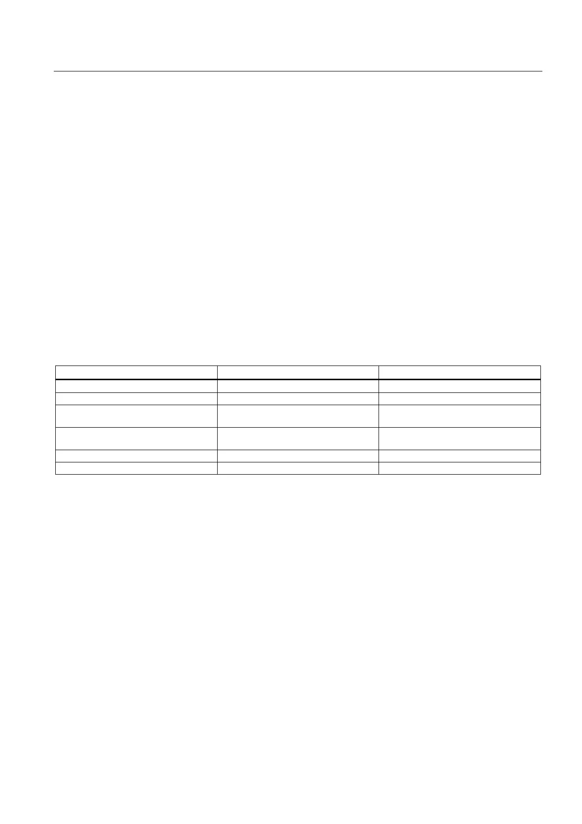
5.5.6 Technical specifications
Table 5-10 Technical Specifications
Voltage Clamping Module
Electronics power supply V
DC
24 (20.4 - 28.8)
DC link voltage V
DC
510 - 750
DC link busbar current carrying
capacity
A 100
24 V busbar
current carrying capacity
A 20
Power loss
1
W 50
Weight kg 3.1
1
For an overview, see the power loss tables in Cabinet Design.

 Loading...


