Motor Modules Booksize
4.2 Motor Modules with Internal Air Cooling
Equipment Manuel for Booksize Power Modules
Manual, (GH2), Edition 06.2005, 6SL3097-2AC00-0BP2
4-7
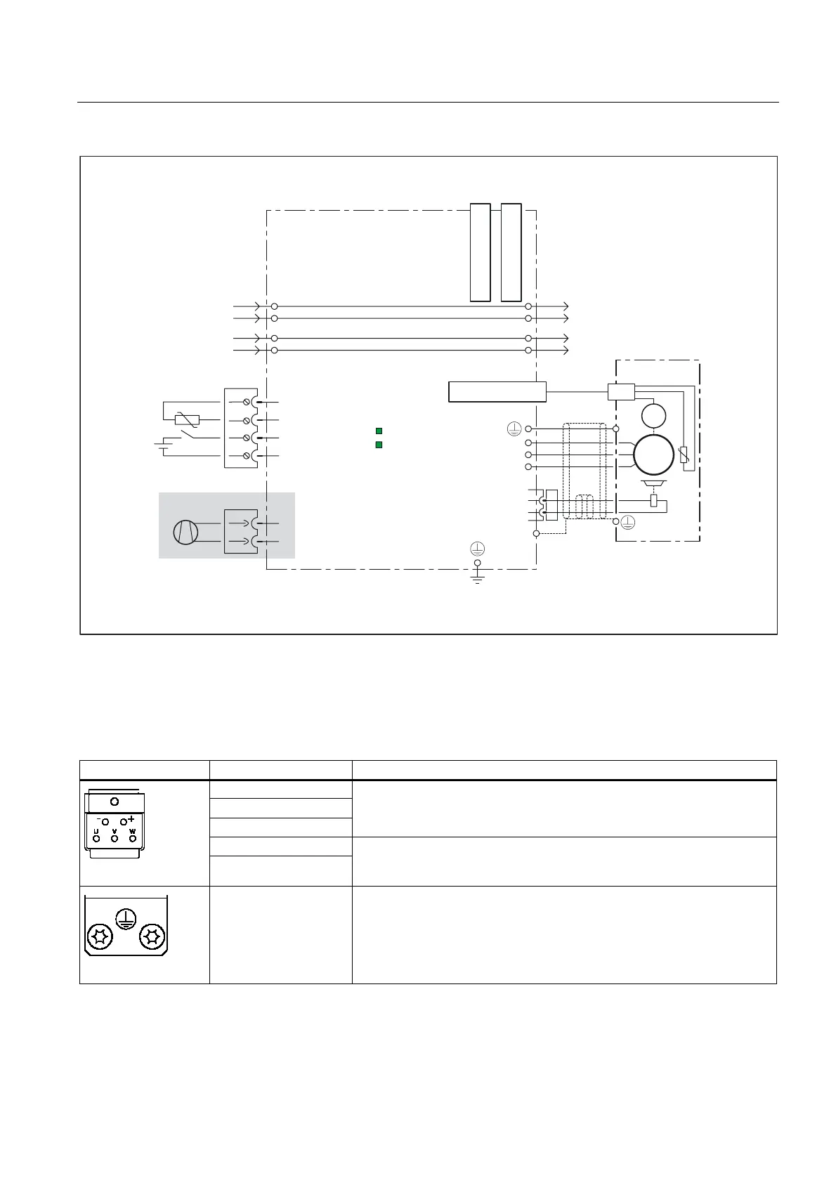
X201X200
M
+
DCN
DCP
M
+
DCN
DCP
2
1
U2
V2
BR+
W2
BR-
X202
~
M
3
I
X11
2)
READY
DC LINK
LEDs
+Temp
X21
4
3
2
1
-Temp
EP M1
EP +24 V
+
X12
2
1
-
1)
3)
˽
˽
mm_large_connection_example.vsd
Motor module
Fan
DRIVE-CLiQ socket 0
DRIVE-CLiQ
socket 1
DRIVE-CLiQ socket 2
1) Required if the Safety function is active
2) Additionally for motor modules 132 A to 200 A
3) Contact via shield plate
Figure 4-4 Connection example of Single Motor Modules 45 A to 200 A
4.2.3.3 Motor/brake connection
Table 4-1 Terminal block X1/X2 Motor Modules 3 A to 30 A and 2x3 A to 2x18 A
Terminal Technical specifications
U (U2)
V (V2)
W (W2)
Motor connection
+ (BR+)
- (BR-)
Brake connection
PE connection Threaded hole M5/3 Nm
1
1
for ring cable lugs to DIN 46234

 Loading...


