Cabinet Configuration and EMC Booksize
7.5 Information about electromagnetic compatibility (EMC) and cable laying
Equipment Manuel for Booksize Power Modules
7-24 Manual, (GH2), Edition 06.2005, 6SL3097-2AC00-0BP2
7.5.3 Equipotential bonding
The SINAMICS S booksize drive system is designed for use in cabinets with a PE conductor
connection.
If the drive line-up is arranged on a common unpainted metal-surfaced mounting plate, e.g.
with a galvanized surface, no additional equipotential bonding is needed within the drive line-
up as:
• All parts of the switchgear assembly are connected to the protective conductor system.
• The mounting plate is connected with the external PE conductor by means of a finely-
stranded copper conductor with a cross-section of 16 mm², including the outer conductor.
As of a cross-section of 25 mm² copper, the outer cross-section of the finely-stranded
conductor is halved.
For other installation methods, equipotential bonding must be implemented using conductor
cross-sections as stated in the second item in the list or at least equal to the conductance.
If components are mounted on DIN rails, the data listed in the second item applies for
equipotential bonding. If only smaller connection cross-sections are permissible on
components, the largest must be used (e.g. 6 mm
2
for TM31 and SMC). These requirements
also apply to distributed components located outside the cabinet.
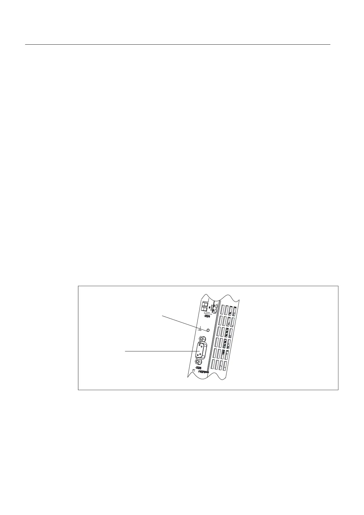
If, for example, the PROFIBUS or DRIVE-CLiQ cable is routed through several cabinets, the
"PROFIBUS equipotential bonding conductor connection" on the control unit interface must
be used for connecting the equipotential bonding conductor. A finely stranded copper
conductor with a 4 mm² cross-section must be used. This conductor must be routed together
with the PROFIBUS cable.
Equipotential Bonding and Shielding for PROFIBUS
The cable shield must be connected over a large contact surface area.
0WKUHDGHGKROHIRUFRQQHFWLQJ
WKHHTXLSRWHQWLDOERQGLQJ
FRQGXFWRUWRWKHIXQFWLRQHDUWK
;
352),%86
Figure 7-7 Functional ground connection for PROFIBUS

 Loading...


