Home
Siemens
Media Converter
SINAMICS Series
Equipment Manual
Page 234 (Dimension Drawing)
Siemens SINAMICS Series - Dimension Drawing
350 pages
Manual
To Next Page
To Next Page
To Previous Page
To Previous Page
Loading...
DC link components Booksize
5.4 Control Supply Module (CSM)
Equipment Manuel for Booksize Power Modules
5-22
Manual, (GH2), Edition 06.2005, 6SL3097-2AC00-0BP2
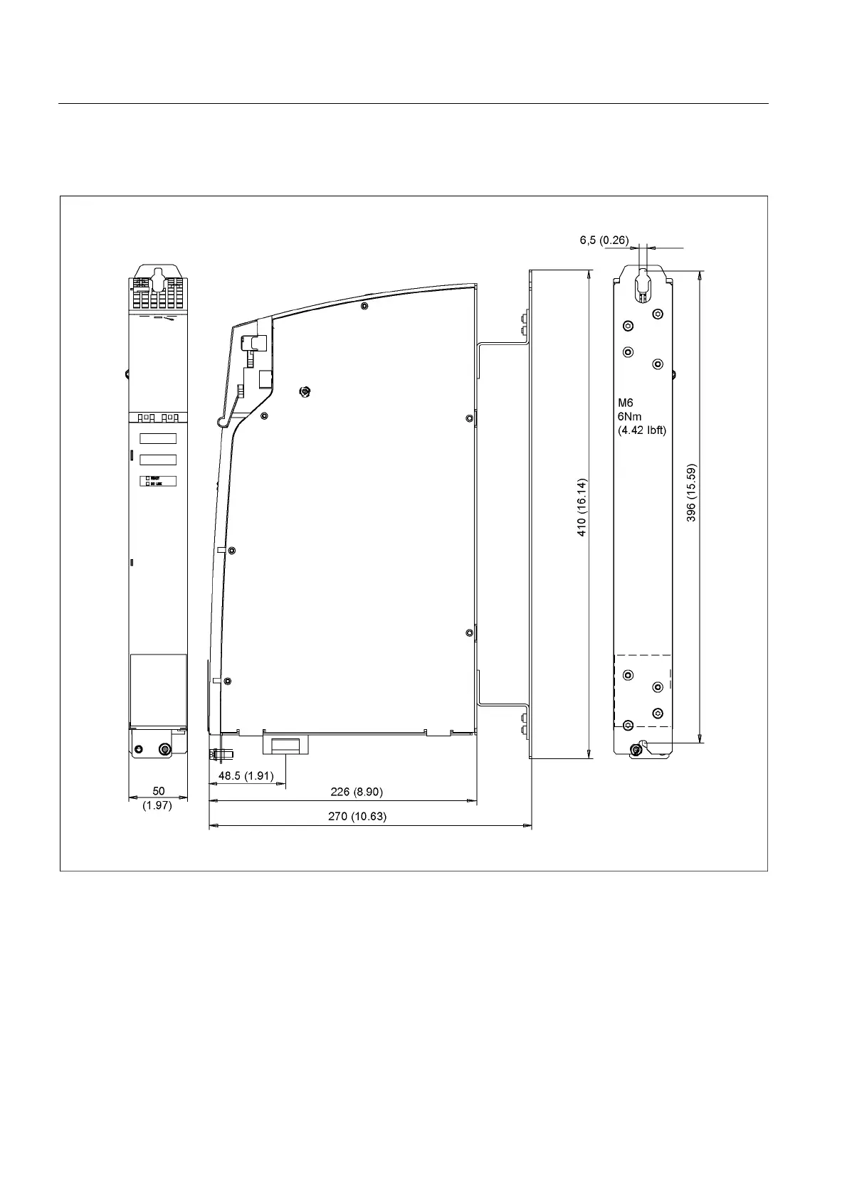
5.4.4
Dimension Drawing
Figure 5-12
Dimension drawing
of the control supply mod
ule
233
235
Table of Contents
Main Page
Default Chapter
11
Table of Contents
11
1 System Overview
17
Field of Application
17
Product Variants
18
Platform Concept and Totally Integrated Automation
19
Introduction
20
SINAMICS S120 Components
23
Power Sections
25
System Data
26
2 Line Connection Booksize
29
Introduction
29
Overview: Line Filters
31
Basic Line Filter for Active Line Modules
32
Description
32
Safety Information
33
Interface Description
34
Overview
34
Line/Load Connection
35
Dimension Drawing
36
Technical Specifications
36
Wideband Line Filter for Active Line Modules
37
Description
37
Safety Information
38
Interface Description
39
Line/Load Connection
40
Dimension Drawing
41
Technical Specifications
42
Line Filters for Smart Line Modules
42
Description
42
Safety Information
43
Interface Description
44
Overview
44
Line/Load Connection
45
Dimension Drawings
46
Technical Specifications
47
Line Reactors for Active Line Modules
48
Description
48
Safety Information
48
Connection Description
49
Line/Load Connection
50
Dimension Drawing
51
Technical Specifications
52
Line Reactors for Smart Line Modules
53
Description
53
Safety Information
53
Connection Description
54
Line/Load Connection
55
Dimension Drawings
56
Technical Specifications
59
Line Connection Variations
60
Methods of Line Connection
60
Operation of the Line Connection Components on the Supply Network
62
Operation of the Line Connection Components Via an Autotransformer
63
Operation of the Line Connection Components Via an Isolating Transformer
65
Line Connection Via a Ground-Fault Circuit Interrupter
67
3 Line Modules Booksize
69
Introduction
69
Active Line Modules with Internal Air Cooling
71
Description
71
Safety Information
72
Interface Description
74
Overview
74
Connection Example
75
X1 Line Connection
76
X200-X202 DRIVE-Cliq Interfaces
77
EP Terminals X21
78
X24 24 V Terminal Adapter
79
Meaning of the Leds on the Active Line Module
79
Dimension Drawing
80
Installation
83
Electrical Connection
85
Technical Specifications
86
Active Line Modules with External Air Cooling
89
Description
89
Safety Information
90
Interface Description
92
Overview
92
Connection Example
93
Line Connection
94
X200-X202 DRIVE-Cliq Interfaces
95
EP Terminals X21
96
Dimension Drawings
98
Installation
100
Electrical Connection
107
Technical Specifications
108
Smart Line Modules (5 Kw and 10 Kw) with Internal Air Cooling
111
Description
111
Safety Information
112
Interface Description
114
Overview
114
Connection Example
115
X1 Line Connection
116
X21 Terminals: Smart Line Module
117
X22 Terminals: Smart Line Module
118
X24 24 V Terminal Adapter
118
Meaning of the Leds on the Smart Line Module
119
Dimension Drawing
120
Installation
121
Electrical Connection
122
Technical Specifications
123
Smart Line Modules (16 Kw and 36 Kw) with Internal Air Cooling
126
Description
126
Safety Information
127
Interface Description
129
Overview
129
Connection Example
131
X1 Line Connection
132
X200-X202 DRIVE-Cliq Interfaces
133
EP Terminals X21
134
X24 24 V Terminal Adapter
134
Meaning of the Leds on the Smart Line Module
135
Dimension Drawings
136
Installation
138
Electrical Connection
139
Technical Specifications
140
Smart Line Modules (5 Kw and 10 Kw) with External Air Cooling
143
Description
143
Safety Information
144
Interface Description
146
Overview
146
Connection Example
147
X1 Line Connection
148
X21 Terminals: Smart Line Module
149
X22 Terminals: Smart Line Module
150
X24 24 V Terminal Adapter
150
Meaning of the Leds on the Smart Line Module
151
Dimension Drawing
152
Installation
153
Electrical Connection
159
Technical Specifications
160
4 Motor Modules Booksize
163
Introduction
163
Motor Modules with Internal Air Cooling
164
Description
164
Safety Information
165
Interface Description
167
Overview
167
Connection Examples
168
Motor/Brake Connection
169
X21/X22 EP Terminals/Temperature Sensor Connection Motor Module
171
X200-X203 DRIVE-Cliq Interface
171
Meaning of the Leds on the Motor Module
172
Dimension Drawings
173
Installation
177
Electrical Connection
178
Technical Specifications
179
Motor Module with External Air Cooling
185
Description
185
Safety Information
186
Interface Description
188
Overview
188
Connection Examples
189
Motor/Brake Connection
190
X21/X22 EP Terminals/Temperature Sensor Connection Motor Module
192
X200-X203 DRIVE-Cliq Interface
192
Meaning of the Leds on the Motor Module
193
Dimension Drawing
194
Installation
198
Electrical Connection
205
Technical Specifications
206
600 DC Link Components Booksize
213
Braking Module Booksize
213
Description
213
Safety Information
214
Interface Description
215
Overview
215
Connection Example
216
Braking Resistor Connection X1
217
X21 Digital Inputs/Outputs
217
Meaning of the Leds on the Braking Module
218
Dimension Drawing
219
Mounting
220
Technical Specifications
221
Braking Resistors
222
Capacitor Module
224
Description
224
Safety Information
224
Interface Description
225
Overview
225
Dimension Drawing
226
Installation
227
Technical Specifications
228
Control Supply Module (CSM)
229
Description
229
Safety Information
230
Interface Description
231
Overview
231
Connection Example
232
Options
232
Meaning of the Leds on the Control Supply Module
233
Dimension Drawing
234
Technical Specifications
235
Voltage Clamping Module (VCM)
236
Description
236
Safety Information
237
Interface Description
238
Overview
238
X1 Functional Ground
239
Dimension Drawing
240
Installation
241
Technical Specifications
241
6 Options
243
Shielded Terminal Plates
243
Description
243
Overview
244
Dimension Drawings
246
Installation
254
Electrical Connection
257
DC Link Supply Adapter
259
Description
259
Safety Information
260
Interface Description
261
Overview
261
DC Link Connection
262
Dimension Drawings
263
Installation
265
Electrical Connection
268
DC Link Adapter
269
Description
269
Safety Information
269
Interface Description
270
Overview
270
DC Link Connection
271
Dimension Drawing
272
Installation
273
Electrical Connection
274
DRIVE-Cliq Flanged Coupling
275
Description
275
Safety Information
275
Interface Description
276
Overview
276
Dimension Drawing
277
Installation
278
Technical Specifications
279
DRIVE-Cliq Coupling
279
Description
279
Safety Information
279
Interface Description
280
Overview
280
Dimension Drawing
280
Installation
281
Technical Specifications
281
7 Cabinet Configuration and EMC Booksize
283
Information
283
General
283
Safety Information
284
Directives and Standards
285
Selection of Devices Required for Operation of SINAMICS
286
General
286
Information about Line Isolating Devices
286
Overcurrent Protection by Means of Line Fuses or Circuit-Breakers
287
Line Contactors
288
DC Supply Voltage
288
General
288
Selection of Power Supply Units
290
Typical 24-V Component Power Consumption
291
Overcurrent Protection
293
Arrangement of Components and Devices
296
General
296
Drive Line-Up
296
Information about Electromagnetic Compatibility (EMC) and Cable Laying
302
General
302
Cable Shielding and Routing
303
Equipotential Bonding
306
Connection Methods
307
Spring-Loaded Terminals/Screw Terminals
307
Motor Connector
309
Power Connector (X1/X2)
311
24-V Terminal Adapter
313
Cooling
314
General
314
Information about Ventilation
320
Power Loss of Components in Rated Operation
321
Dimensioning Climate Control Equipment
326
8 Service and Support Booksize
327
Technical Support
327
Replacing Fans
327
Spare Parts
329
List of Abbreviations
334
References
339
Index
343
Other manuals for Siemens SINAMICS Series
Operating Instructions
758 pages
Function Manual
102 pages
Quick Install Guide
2 pages
Related product manuals
Siemens SINAMICS DCM
758 pages
Siemens sinamics dcp
518 pages
Siemens SINAMICS G150
1842 pages
Siemens SINAMICS S110
268 pages
Siemens SINAMICS G220
834 pages
Siemens SINAMICS G120X
1148 pages
Siemens SINAMICS G120D
382 pages
Siemens SINAMICS G110M
428 pages
Siemens SINAMICS G120XA
918 pages
Siemens SINAMICS G120C USS/MB
470 pages
Siemens SINAMICS G120D Series
326 pages
Siemens SINAMICS G120 PM240P-2
106 pages

 Loading...


