DC link components Booksize
5.5 Voltage Clamping Module (VCM)
Equipment Manuel for Booksize Power Modules
Manual, (GH2), Edition 06.2005, 6SL3097-2AC00-0BP2
5-27
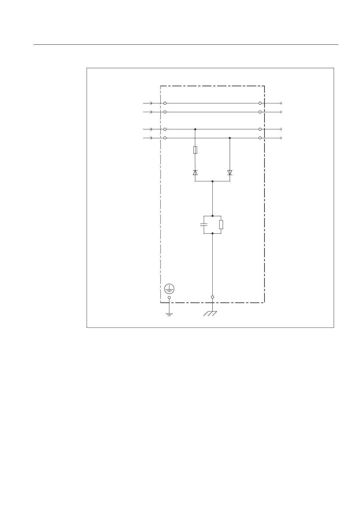
9ROWDJH&ODPSLQJ0RGXOH
;
'&3
'&1
'&3
'&1
0
0
Figure 5-14 Circuit diagram: Voltage Clamping Module
5.5.3.2 X1 functional ground
X1 functional ground
To ensure that the Voltage Clamping Module functions properly, a functional ground must be
connected to X1. Please note:
• The cables must be routed via the shortest possible path.
• Cross-section: 4 mm² to 16 mm²
• When a line filter is used, the functional ground should be located on the metallic
installation panel in the immediate vicinity of the line filter.
• In systems without a line filter, it should be connected on the PE busbar.

 Loading...


