Motor Modules Booksize
4.3 Motor Module with external air cooling
Equipment Manuel for Booksize Power Modules
Manual, (GH2), Edition 06.2005, 6SL3097-2AC00-0BP2
4-31
4.3.3.6 Meaning of the LEDs on the motor module
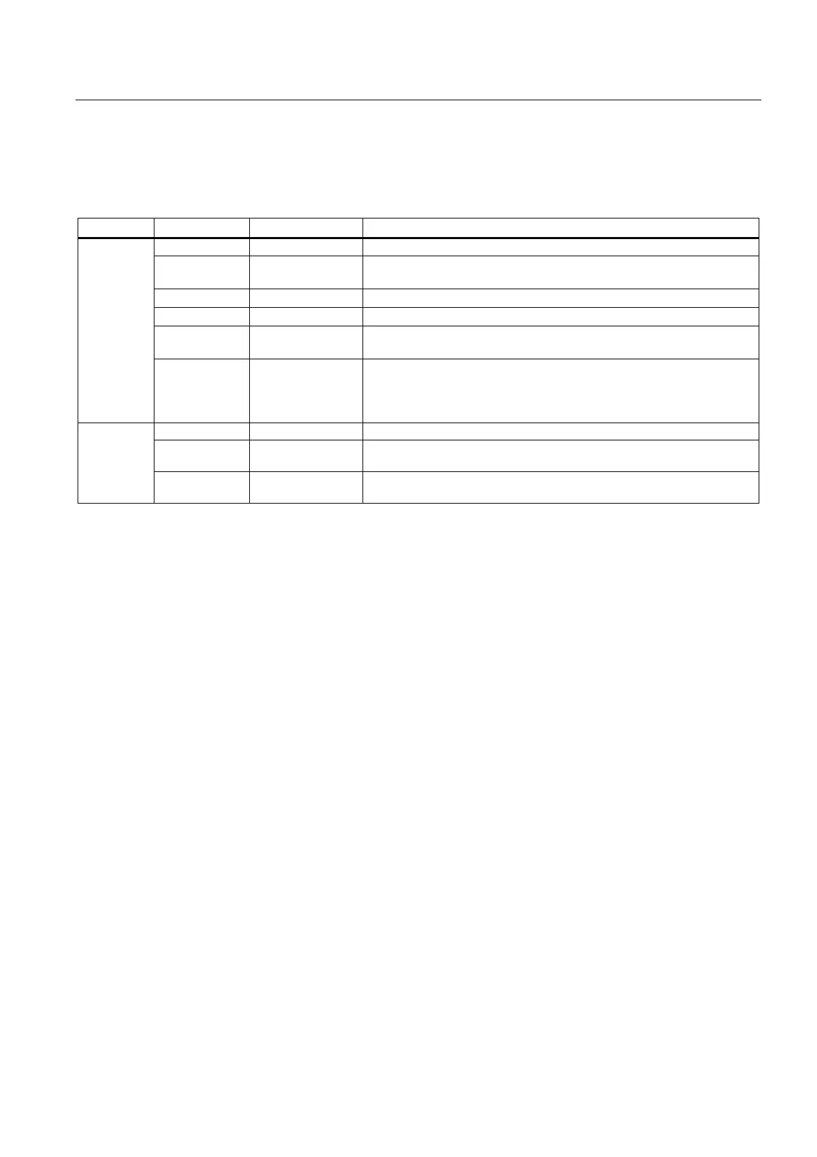
Table 4-16 Meaning of the LEDs on the Motor Module
LED Color State Description
- OFF Electronics power supply outside permissible tolerance range.
Green Continuous The component is ready for operation and cyclic DRIVE-CLiQ
communication is taking place.
Orange Continuous DRIVE-CLiQ communication is being established.
Red Continuous At least one fault is present in this component.
Green
Red
Flashing
2 Hz
Firmware is being downloaded.
READY
Green/Orange
or Red/Orange
Flashing
2 Hz
Component recognition via LED is activated (p0124).
Note:
Both options depend on the LED status when module recognition is
activated via p0124 = 1.
- OFF Electronics power supply outside permissible tolerance range.
Orange Continuous DC link voltage within permissible tolerance range (only when ready
for operation)
DC LINK
Red Continuous DC link voltage outside permissible tolerance range (only when ready
for operation)
Cause and rectification of faults
The following reference contains information about the cause and rectification of faults:
Reference: /IH1/ SINAMICS S120 Commissioning Manual

 Loading...


