DC link components Booksize
5.1 Braking Module Booksize
Equipment Manuel for Booksize Power Modules
5-6 Manual, (GH2), Edition 06.2005, 6SL3097-2AC00-0BP2
5.1.3.5 Meaning of the LEDs on the braking module
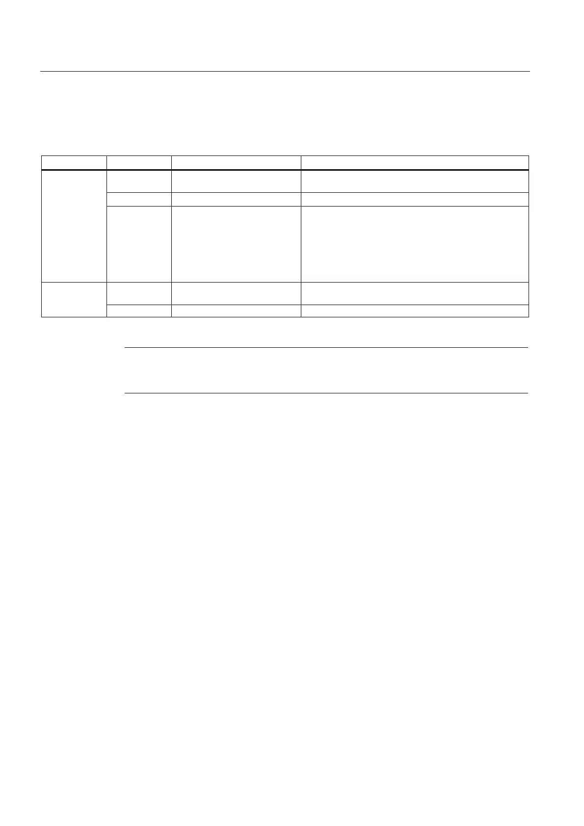
Table 5-3 Meaning of the LEDs on the braking module
LED Color State Description
- OFF Electronics power supply outside permissible tolerance
range.
Green Continuous The component is ready for operation.
READY
Red Continuous
• Braking module inhibited via DI X21.1
• Braking module shutdown
Possible reasons:
– Overcurrent
– Overtemperature heat sink
– Braking resistor overload (I*t shutdown)
- OFF Braking resistor switched off (DC link discharge not
active)
DC LINK
Green Flashing Braking resistor switched on (DC link discharge active)
Note
To protect the braking resistor, the current fault cannot be acknowledged until after a waiting
period of approx. 3 min after an I*t shutdown of the braking module.

 Loading...


