Line Modules Booksize
3.2 Active Line Modules with Internal Air Cooling
Equipment Manuel for Booksize Power Modules
3-10 Manual, (GH2), Edition 06.2005, 6SL3097-2AC00-0BP2
3.2.3.5 EP terminals X21
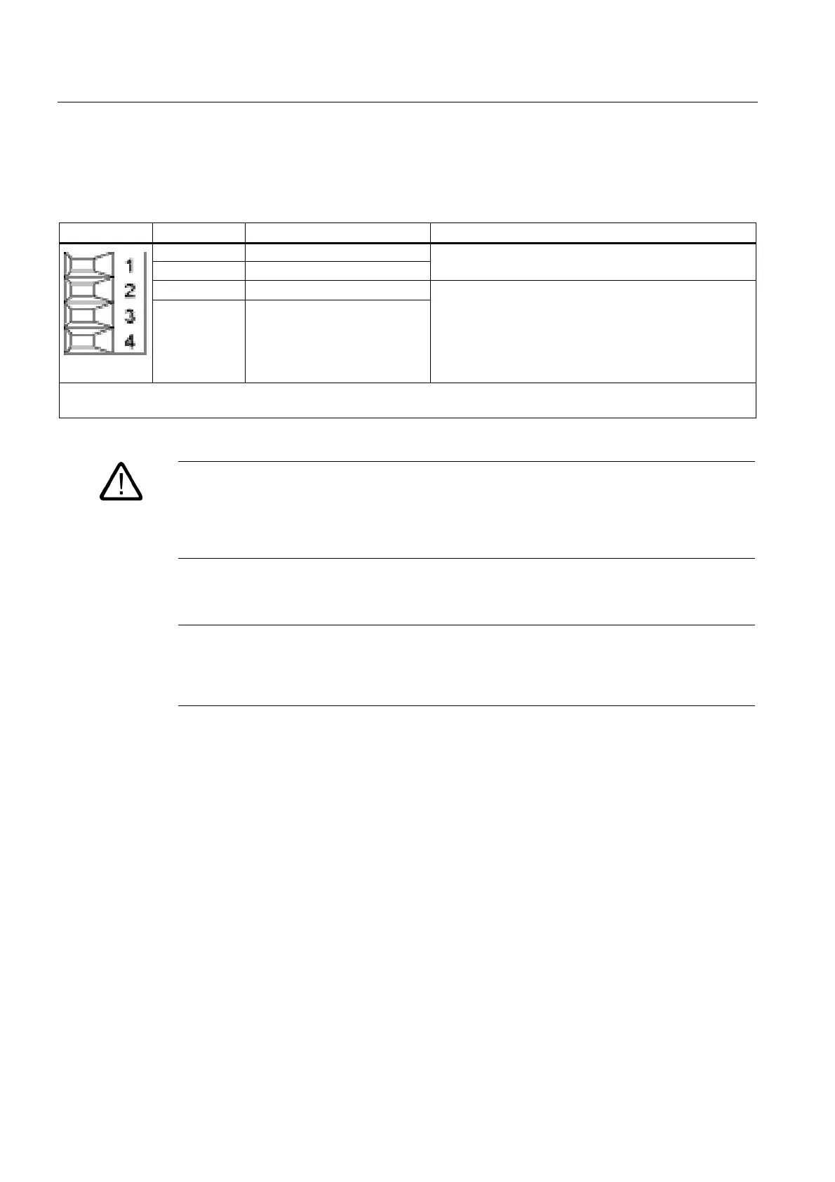
Table 3-4 Terminal block X21
Terminal Name Technical specifications
1 Reserved, do not use
2 Reserved, do not use
3 EP +24 V (Enable Pulses)
4 EP M (Enable Pulses)
Voltage 24 V DC
Current consumption: 10 mA
Isolated input
Signal propagation times:
L → H 100 μs
H → L: 1000 μs
Max. connectable cross-section: 1.5 mm
2
Type: Screw terminal 1 (see Connection Methods)
Warning
For operation, 24 V DC must be connected to terminal 3 and ground to terminal 4. Upon
removal, pulse inhibit is activated. Feedback is deactivated and the bypass relay drops out.
If the Line Module is not disconnected from the network when the EP terminal is deactivated
(e.g. a main contactor is not installed), the DC link remains charged.
Notice
If a drive line-up is switched off by means of the line disconnecting device, the voltage at
terminals 3 (EP +24 V) and 4 (EP M) must be interrupted beforehand. This can be carried
out using a leading breaking auxiliary contact (≥ 10 ms), for example.

 Loading...


