EasyManuals Logo

Siemens SINAMICS Series Equipment Manual

Siemens SINAMICS Series
350 pages
To Next Page IconTo Next Page
To Previous Page IconTo Previous Page
Page #273 background imageLoading...
Page #273 background image
Options
6.3 DC link adapter
Equipment Manuel for Booksize Power Modules
Manual, (GH2), Edition 06.2005, 6SL3097-2AC00-0BP2
6-31
6.3.5 Installation
Required tools:
• Torx screwdriver T20
• Flat-bladed screwdriver 1 (0.5 – 3.5)
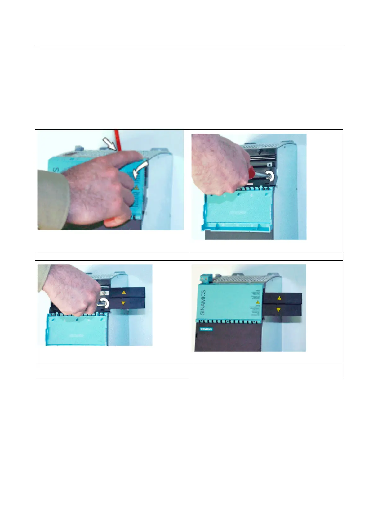
Table 6-13 Installing the DC link adapter for a 150 mm module
Unlock and open the protective cover. Unscrew the screws.
Secure the adapter (1.8 Nm). The 24 V adapter is installed
and the protective cover is closed.
Note:
By moving the adapter housing, the DC link adapter can be fitted on either the left-hand or
right-hand side of the module. This is possible with Active Line Modules as of 55 kW; see
overview below.

Table of Contents

Other manuals for Siemens SINAMICS Series

Questions and Answers:

Question and Answer IconNeed help?

Do you have a question about the Siemens SINAMICS Series and is the answer not in the manual?

Siemens SINAMICS Series Specifications

General IconGeneral
Product LineSINAMICS
Cooling MethodAir-cooled, Liquid-cooled
Voltage Range200 V to 690 V
Power Range0.12kW - 250kW
Communication InterfacesPROFINET, PROFIBUS, Ethernet
Control ModesVector control, V/f control
Protection ClassIP20
TypeVariable Frequency Drives (VFD)

Related product manuals