Options
6.3 DC link adapter
Equipment Manuel for Booksize Power Modules
6-32 Manual, (GH2), Edition 06.2005, 6SL3097-2AC00-0BP2
Table 6-14 Overview
Active Line Module Internal cooling External cooling
55 kW 6SL3130-7TE25-5AA2 6SL3131-7TE25-5AA0
(only with DC link busbars)
80 kW 6SL3130-7TE28-0AA1 6SL3131-7TE28-0AA0
(only with DC link busbars)
120 kW 6SL3130-7TE31-2AA1 6SL3131-7TE31-2AA0
(only with DC link busbars)
6.3.6 Electrical Connection
Required tools:
• Hexagon-socket spanner (size 6)
• Suitable tool for tube clips (e.g. flat-bladed screwdriver)
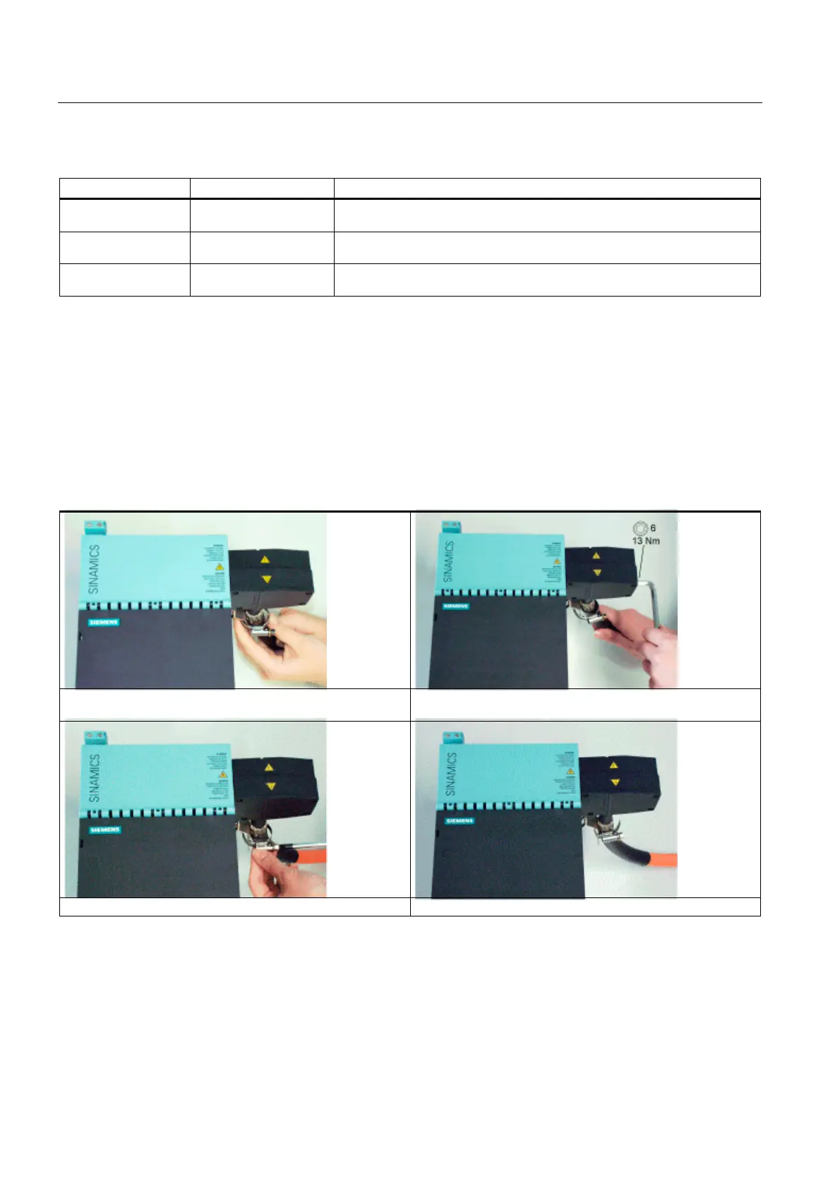
Table 6-15 Electrical connection of the DC link adapter for a 150 mm module
Route the cable through the tube clip and insert it into the
DC link adapter.
Secure the cable.
Secure the tube clip. The cable is connected.
Only shielded connection cables should be used.
The DC link adapter can be fitted on the right or left.

 Loading...


