Motor Modules Booksize
4.3 Motor Module with external air cooling
Equipment Manuel for Booksize Power Modules
Manual, (GH2), Edition 06.2005, 6SL3097-2AC00-0BP2
4-29
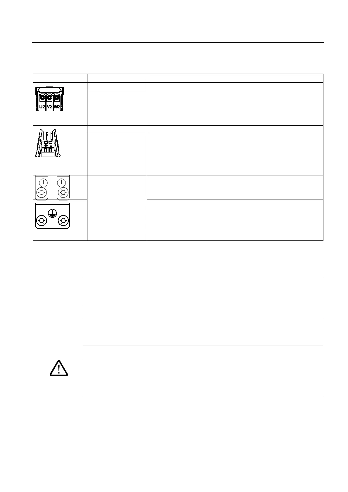
Table 4-13 Terminal block Single Motor Module 45 A to 200 A
Terminals Technical specifications
U2
V2
W2
45 A to 60 A:
Threaded bolt M6/6 Nm
1
85 A:
Threaded bolt M8/13 Nm
1
132 A to 200 A:
Threaded bolt M8/13 Nm
1
+ (BR+)
- (BR-)
X11 brake connector
2
:
Voltage: 24 V DC
Max. load current: 2 A
Min. load current: 0.1 A
Max. connectable cross-section: 2.5 mm
2
Type: Spring-loaded terminal 2 (see Connection Methods)
Manufacturer: Wago; order number: 721-102/026-000/56-000
The brake connector is part of the prefabricated cable.
Single Motor Module with a rated output current of 45 A to 60:
Threaded bolt for motor cables: M6/6 Nm
1
Threaded hole for PE: M6/6 Nm
1
PE connection
Single Motor Module with a rated output current of 85 A
Threaded bolt for motor cables: M8/13 Nm
1
Threaded hole for PE: M6/6 Nm
1
Single Motor Module with a rated output current of 132 A to 200 A
Threaded bolt for motor cables: M8/13 Nm
1
Threaded hole for PE: M8/6 Nm
1
1
For ring cable lugs to DIN 46234
2
The circuit for protecting the brakes against overvoltage is in the Motor Module and does not need to be installed externally. The max. load
current is 2 A, the min. load current 0.1 A.
Note
The total length of the shielded power cables (motor supply cables and DC link cables) must
not exceed 350 m.
Note
The motor brake must be connected via connector X11. The BR- cable must not be
connected directly to electronic ground (M).
Warning
Only protective extra-low voltages (PELVs) that comply with EN60204-1 must be connected
to all connections and terminals between 0 and 48 V DC.
The voltage tolerances of the motor holding brakes must be taken into account.

 Loading...


