373
2
Press [Dual M/E Assign].
The unshifted state is assigned as cross-points on the
M/E bank with the selected bank number, and the
shifted state is assigned as cross-points on the M/E
bank with the next consecutive bank number.
The shift/unshifted assignments can be interchanged
using [Dual M/E Xpt Swap].
To return to the original assignment
Set the bank configuration (see page 372).
Interchanging shifted and non-shifted
operations for a dual M/E
1
In the Engineering Setup >Panel >Config menu
(7321), select the M/E banks configured for dual M/E.
2
Press [Dual M/E Xpt Swap], toggling the setting.
When [Dual M/E Xpt Swap] is lit: The M/E bank
toward the front (larger bank number) is the
unshifted state, and the M/E bank toward the rear
is the shifted state.
When [Dual M/E Xpt Swap] is not lit: The M/E bank
toward the rear (smaller bank number) is the
unshifted state, and the M/E bank toward the front
is the shifted state.
Linking Switcher Bus and Router
Destinations
To link the switcher bus and router destination, make the
following settings as required.
Matrix selection: Select the target of the link setting from
the eight-point matrix (1 to 8).
Matrix position definition: Set the start address and level
for the source and destination on the S-Bus.
Link table setting: Link a switcher cross-point button and
matrix source.
Link bus setting: Link a switcher bus address and router
destination.
Selecting a matrix number
1
In the Engineering Setup >Panel >Config menu
(7321), press [Link/Program Button].
The Link/Program Button menu (7321.8) appears.
2
In the <Link> group, press [External Bus Link].
The External Bus Link menu (7321.3) appears.
3
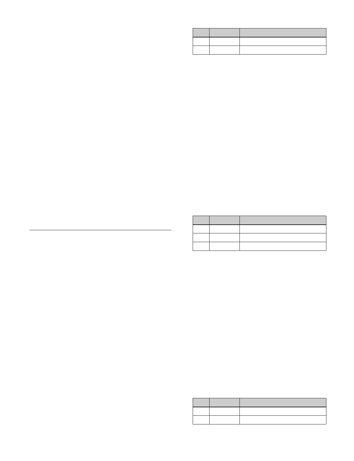
Set the following parameters.
4
Press [Link Matrix Set].
To release the link
Select the link to release, then press [Clear].
Defining the position of a matrix
Specify where in the 1024×1024 S-Bus space the link
matrix is to be provided by setting the source and
destination start addresses.
Make settings for the matrix selected in the External Bus
Link menu.
1
In the Engineering Setup >Panel >Config >Link/
Program Button >External Bus Link menu (7321.3),
press [Link Matrix Adjust].
The Link Matrix Adjust menu (7321.4) appears.
You can also select the matrix in this menu using the
[Link Matrix] parameter.
2
Define the position of the matrix.
3
Perform the following operations.
• To apply the source address, press [Source Set].
• To apply the destination address, press [Destination
Set].
• To apply the level, press [Level Set].
Setting a link table
Make settings for the link number selected in the External
Bus Link menu.
1
In the Engineering Setup >Panel >Config >Link/
Program Button >External Bus Link >Link Matrix
Adjust menu (7321.4), press [Link Table Adjust].
The Link Table Adjust menu (7321.5) appears.
2
Select the switcher cross-point button and the matrix
source to be linked to the button.
No. Parameter Adjustment
1 Link No Link number
2 Link Matrix Matrix number to link
No. Parameter Adjustment
2 Source Source start address
3 Destination Destination start address
4 Level Level
No. Parameter Adjustment
1 Main No Switcher cross-point button
2 Source No Matrix source selection

 Loading...