90
Fader Lever Operation in Bus Fixed
Mode
Flip-flop mode and bus fixed mode
This section describes flip-flop mode and bus fixed mode
on an M/E bank, as an example. The functionality is the
same on the PGM/PST bank.
Normally, when a background transition is executed on an
M/E bank, the signals selected on the 3rd row (background
A bus) and 4th row (background B bus) are interchanged
at the end of the transition. That is to say, except during a
transition, the background output is always from the
background A bus. This is called “flip-flop mode.”
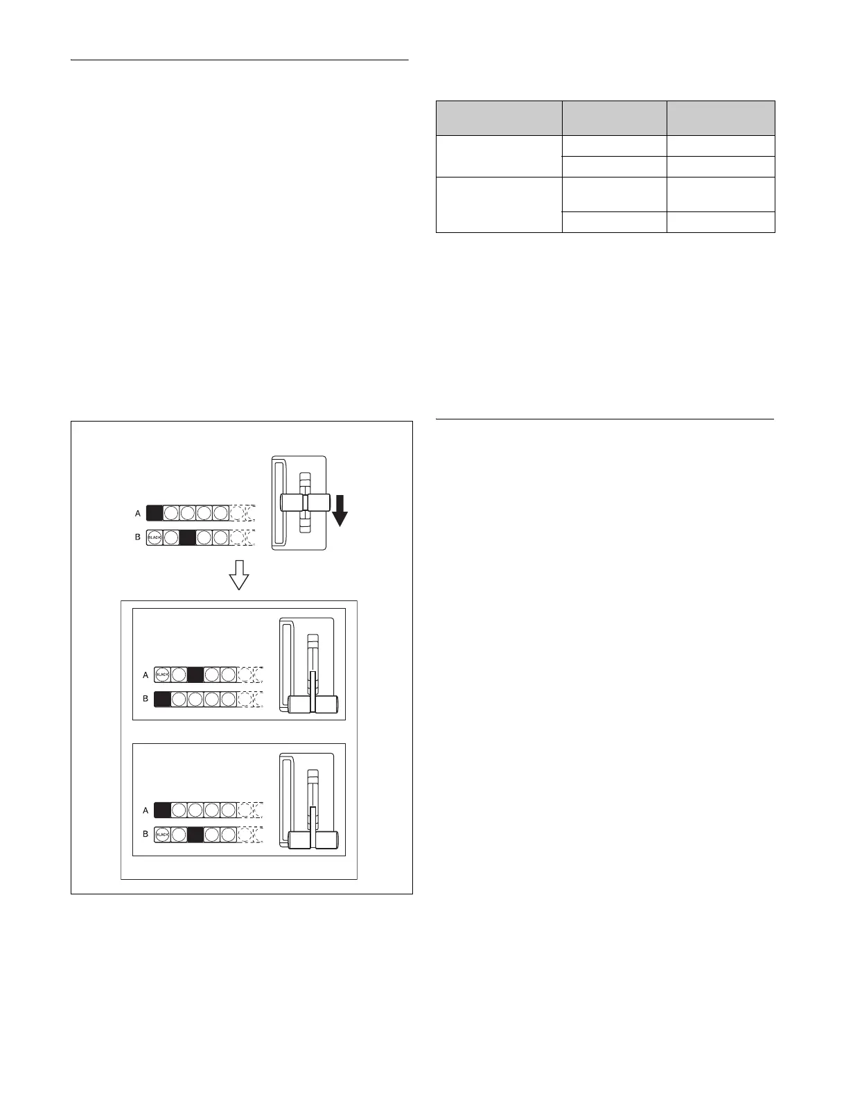
The alternative is known as “bus fixed mode,” in which
there is no bus interchange between the A bus and B bus
signals. In this mode, when the fader lever is at the top of
its travel the output from the A bus is always 100%, and
when the fader lever is at the bottom of its travel the output
from the B bus is 100%.
In bus fixed mode, there is a fixed relationship between the
position of the fader lever and the signal output on the
background A bus and background B bus. When executing
a manual transition, the fader lever must therefore always
be moved in the directions shown in the following table
according to the transition direction. This does not affect
an auto transition, which can always be executed
regardless of the fader lever direction.
• When a transition uses a combination of more than one
of the background and key 1 to key 8, then the transition
for all of these must be in the same direction complying
with the above table.
• If as a result of an auto transition, for example, the fader
lever position does not agree with the signal output of
each bus, a non-sync state (see page 89) results and
LEDs light/flash at both end positions of the fader lever
travel.
Split Fader
Split fader is a function that splits a single fader lever into
left and right, allowing you to control background A bus
and background B bus transitions independently.
The fader lever on the transition control block (simple
type) is split into two by pressing the lock button to unlock
the two fader levers for use as split faders.
The split fader levers support the following buses. You can
change the settings in the Setup menu.
• Right fader lever: Background A bus (main)
• Left fader lever: Background B bus
The following conditions must be satisfied in order to use
the fader lever as split faders.
• Bus fixed mode is set.
• Split faders are enabled.
• Mix or NAM (non-additive mix) is selected for
transition type.
• If the transition type is a clip transition, Mix or NAM
(non-additive mix) is selected for the background
transition type.
If these conditions are not satisfied, only the main
(background A bus) fader lever can be operated.
For details about split fader settings, see “Setting the Main
Fader Lever” (page 392) and “Enabling/disabling split
faders” (page 412).
Split fader operation
The relationship between the position of the fader lever
and the output for a mix transition type is given below.
Lit buttons
Fader lever
Flip-flop mode
Bus fixed mode
Next transition Transition
direction
Fader lever
movement
Background A t B Top t Bottom
B t A Bottom t Top
Key 1 to key 8 On t Off
(remove)
Top t Bottom
Off t On (insert) Bottom t Top