Chapter
22
427
Router Interface and
Tally Setup
Router Interface Settings
In this system, the interface with a router (routing
switcher) uses the S-Bus protocol. It is therefore necessary
to assign inputs and outputs of the switcher and so on to S-
Bus space.
The settings used are common to both parallel and serial
tallies.
Assigning Switcher Inputs/Outputs
to S-Bus Space
Assign the switcher matrix to S-Bus space, and then select
the matrix size and positioning level, source address
settings, and so on.
1
In the <Device> group of the Engineering Setup
>Router/Tally >Router menu (7361), select the target
device to set.
SWR1: Settings apply to switcher 1.
SWR2: Settings apply to switcher 2.
When there are two switchers on the same network, the
SWR2 (second switcher) settings are required. If there
is only one switcher, the settings are not required.
2
In the <Matrix Size> group, select the matrix size.
320×348 (Standard): Assign the switcher input/
outputs to S-Bus space at 320×348 size.
274×254: Assign the switcher input/outputs to S-Bus
space at 274×254 size.
272×274: Assign the switcher input/outputs to S-Bus
space at 272×274 size.
182×256: Assign the switcher input/outputs to S-Bus
space at 182×256 size.
136×138: Assign the switcher input/outputs to S-Bus
space at 136×138 size.
128×128: Assign the switcher input/outputs to S-Bus
space at 128×128 size.
3
Set the following parameters.
Setting External Boxes 1 to 12
To obtain the signal selection status of external devices
with a parallel input, assign a matrix as an external selector
to S-Bus space. Configure the matrix size, assignment
level, source address, and other settings.
1
In the Engineering Setup >Router/Tally >Router menu
(7361), press [External Box Assign].
The External Box Assign menu (7361.1) appears.
2
In the <Device> group, select the target to set
(External Box 1 to 12).
3
In the <Matrix Size> group, select the number of
inputs for the external box.
No Assign: Do not use.
4×1: 4 inputs and 1 output
8×1: 8 inputs and 1 output
16×1: 16 inputs and 1 output
32×1: 32 inputs and 1 output
The maximum total number of inputs for all 12
external boxes is 102.
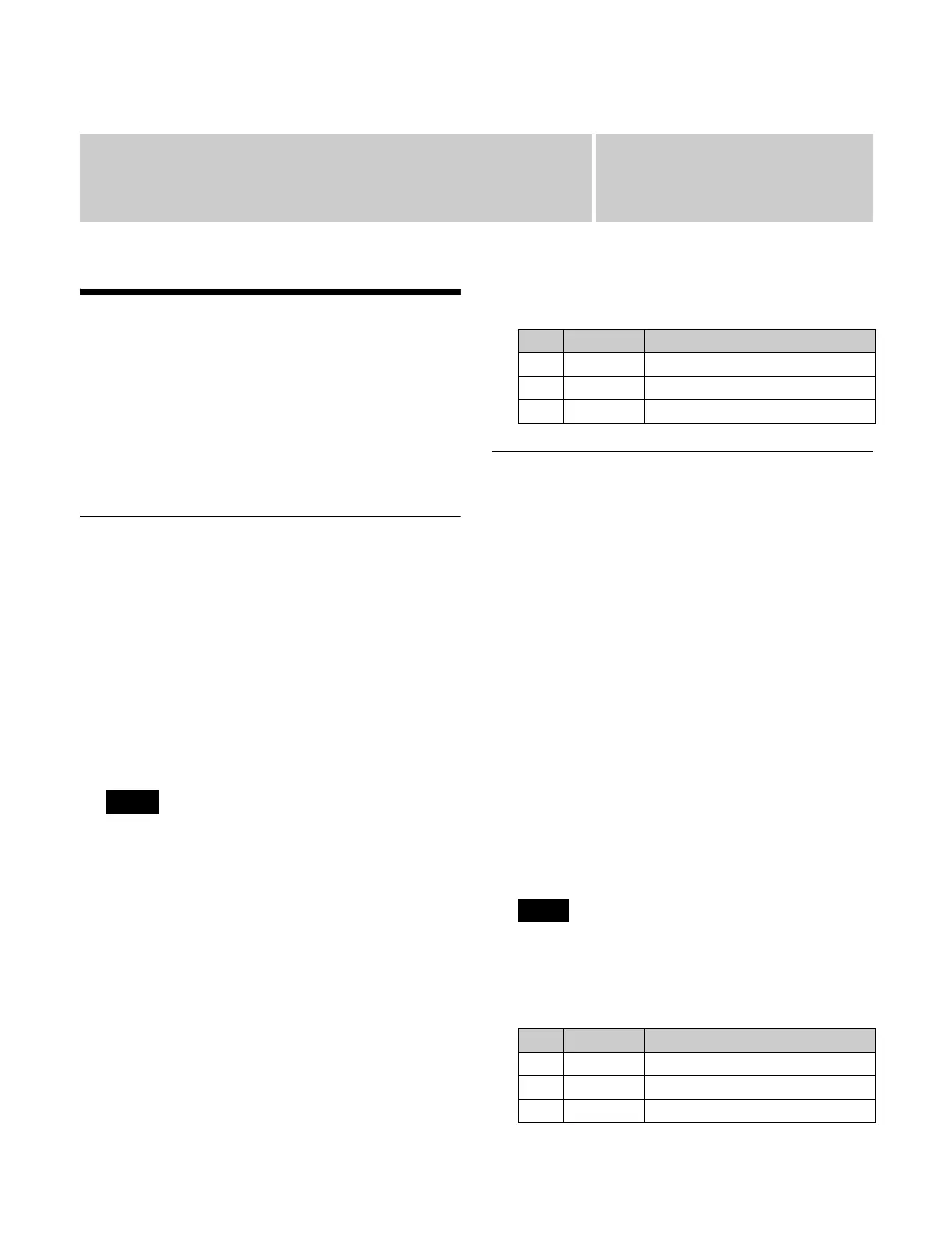
4
Set the following parameters.
Note
No. Parameter Adjustment
1 Source Source start address
2 Destination Destination start address
3 Level S-Bus level
Note
No. Parameter Adjustment
1 Source Source start address
2 Destination Destination start address
3 Level S-Bus level