421
4
In the <Parallel Output Assign> group, press [No
Assign].
GPI Output Settings
Configure the trigger type and other settings for each GPI
output.
Configuring GPI Outputs
1
In the Engineering Setup >DCU >GPI Output Assign
menu (7354), select the target GPI output to set.
2
In the <Trigger Type> group, select the trigger
polarity.
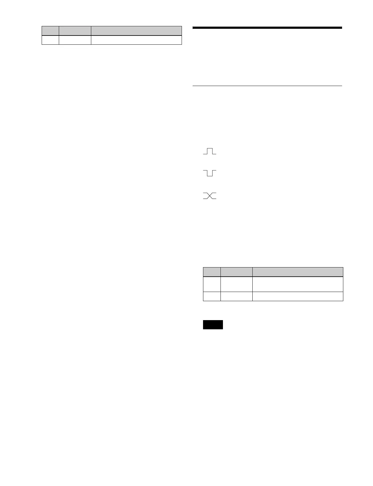
(Rising Edge): Trigger causes the relay to open
or the output to go high level, and holds this state
for the pulse width duration.
(Falling Edge): Trigger causes the relay to close
or the output to go low level, and holds this state
for the pulse width duration.
(Any Edge): When a trigger occurs, the relay
opens/closes or the output goes high/low level,
switching state.
Status: The relay opens/closes or the output goes
high/low level in response to the status.
No Operation: The trigger has no effect on the relay
state or the output level.
3
Set the pulse width and timing.
a) 1: Field 1, 2: Field 2, 3: Any
When “Any Edge” is selected as the trigger type, only
the [Timing] parameter is available. When “Status” is
selected as the trigger type, there are no parameter
settings.
4
In the <Source Device> group, select the control panel
to handle the GPI output.
PNL1: ID1 control panel
PNL2: ID2 control panel
PNL3: ID3 control panel
When the action set in step 5 is executed on the control
panel selected in this step, GPI output occurs. It is also
possible to output error information.
4 To Port Last port number
No. Parameter Adjustment
No. Parameter Adjustment
3Pulse
Width
Pulse width
4 Timing Output timing
a)
Note