470
Content Displayed in
Macro Attachment List
The “Button” column in the macro attachment list
displayed in the status area of the Macro >Attachment
menu (5421) shows the names of buttons that you apply a
macro attachment using symbol abbreviations.
The “Button” column in the list displays a combination of
Button (1), Button (2), and Button (3) from the following
tables.
Example:
Block: P/P XPT
Button (1): UTIL1 Bus
Button (2): V 1st Row
Button (3): XPT2
In this case, the display in the “Button” column is:
UTIL1 Bus V 1st Row XPT2
This indicates “P/P cross-point control block, utility1 bus,
1st row video signal, cross-point button 2.”
M/E and PGM/PST Banks
The following table shows the macro attachment
assignable buttons for the PGM/PST bank.
For the M/E-1 (M/E-2 to M/E-5) bank, “P/P” in the Block
Select and Block columns changes to “M/E-1” to “M/E-5”.
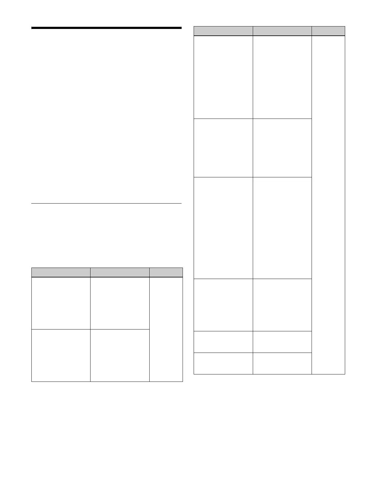
Block Select: P/P, Block: P/P XPT
Button (1) Button (2) Button (3)
A Bus
B Bus
KEY1 Bus
:
KEY8 Bus
1st Row
1st Row Shift
2nd Row
2nd Row Shift
3rd Row
3rd Row Shift
4th Row
4th Row Shift
XPT 1
:
XPT 128
KEY1 Src Bus
:
KEY8 Src Bus
V 1st Row
K 1st Row
V 1st Row Shift
K 1st Row Shift
V 2nd Row
K 2nd Row
V 2nd Row Shift
K 2nd Row Shift
Sub A Bus
Sub B Bus
Sub KEY1 Bus
:
Sub KEY8 Bus
Main&Sub A Bus
Main&Sub B Bus
Main&Sub KEY1 Bus
:
Main&Sub KEY8 Bus
1st Row
1st Row Shift
2nd Row
2nd Row Shift
3rd Row
3rd Row Shift
4th Row
4th Row Shift
XPT 1
:
XPT 128
Sub KEY1 Src Bus
:
Sub KEY8 Src Bus
Main&Sub KEY1 Src
Bus
:
Main&Sub KEY8 Src
Bus
V 1st Row
K 1st Row
V 1st Row Shift
K 1st Row Shift
V 2nd Row
K 2nd Row
V 2nd Row Shift
K 2nd Row Shift
UTIL1 Bus
UTIL2 Bus
DME EXT Bus
DMEUtility1
DMEUtility2
Sub UTIL1 Bus
Sub UTIL2 Bus
Sub DME EXT Bus
Main&Sub UTIL1 Bus
Main&Sub UTIL2 Bus
Main&Sub DME EXT
Bus
V 1st Row
K 1st Row
V 1st Row Shift
K 1st Row Shift
V 2nd Row
K 2nd Row
V 2nd Row Shift
K 2nd Row Shift
V 3rd Row
K 3rd Row
V 3rd Row Shift
K 3rd Row Shift
V 4th Row
K 4th Row
V 4th Row Shift
K 4th Row Shift
EDIT PVW
AUX1
:
AUX48
FM1
FM2
CCR1
CCR2
V 2nd Row
K 2nd Row
V 2nd Row Shift
K 2nd Row Shift
DME1V
:
DME4V
V 2nd Row
V 2nd Row Shift
DME1K
:
DME4K
K 2nd Row
K 2nd Row Shift
Button (1) Button (2) Button (3)

 Loading...


