397
The button numbers and video/key pair numbers of re-
entry buttons is fixed to the following.
The re-entry video/key numbers are set as the pair numbers
by default. Use the defaults as-is, since changing the
settings will make it impossible to select the correct
signals.
Setting the HOME page of the cross-point
pad
This sets the page that is displayed when the [HOME]
button on the cross-point pad is pressed.
1
In the <Bank Select> group of the Engineering Setup
>Panel >Operation >Xpt Module Operation menu
(7326.12), select the target bank to set.
2
In the <Xpt Pad> group, press [Home Page Set].
3
Enter the page number to set (1 to 14) using the
numeric keypad window, then press [Enter].
Copying cross-point pad settings
You can copy the cross-point pad settings on the cross-
point control block/AUX bus control block to another
cross-point pad.
Copying
Press and hold the [XPTPAD COPY] button on the source
cross-point pad, then press the [XPTPAD COPY] button
on the destination cross-point pad.
• The settings for all page button assignments and the
HOME page of the cross-point pad are copied.
• You cannot copy cross-point pad settings between the
cross-point control block and AUX bus control block.
Setting the Display Mode of the
Cross-Point Control Block/AUX Bus
Control Block
This sets the information that appears on the display of the
cross-point control block/AUX bus control block.
The display content and format can be selected for each of
six types of display mode.
1
In the Engineering Setup >Panel >Operation >Xpt
Module Operation menu (7326.12), press [Display
Mode Setting].
The Display Mode Setting menu (7326.15) appears.
The left side shows six display modes, and the right
side shows a list of items to display.
2
In the <Bank Select> group, select the target bank to
set.
3
Select the target display mode to set.
4
To divide the display into upper/lower to display two
pieces of information, press [Split], turning it on.
5
In the list on the right, select the item to display.
6
Perform the following operations.
• When [Split] is not lit, press [Set] in the <Lower
Area> group.
• When [Split] is lit, press [Set] in the <Upper Area>
group to set the display in the upper area, and in the
<Lower Area> group to set the display in the lower
area.
To rename a display mode
The specified name is displayed on the display mode
buttons in the cross-point pad used for display mode
selection.
1
Select the target display mode to set, and press
[Name].
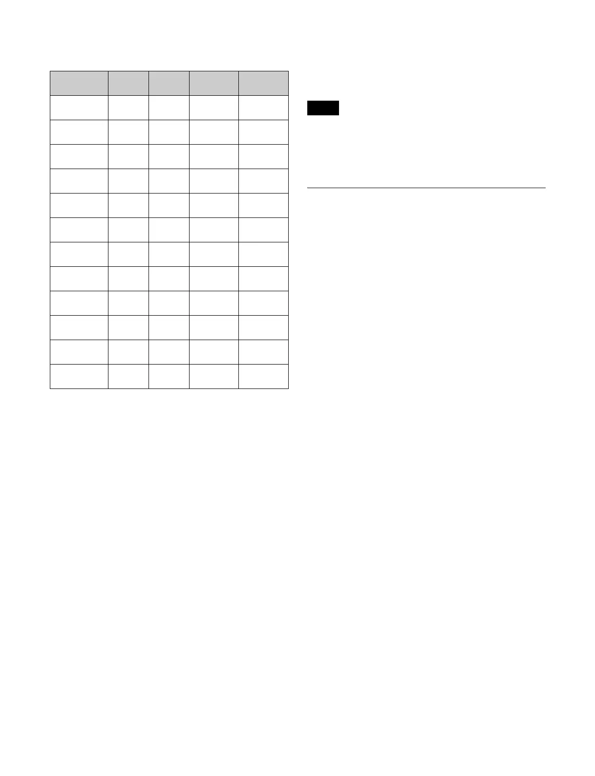
Button name
(n = 1 to 4)
Button
number
V/K pair
number
V default
setting
K default
setting
ROW-n P/P
OUT1
284 211 P/P OUT1 P/P OUT1
ROW-n
M/E-1 OUT1
281 221 M/E-1
OUT1
M/E-1
OUT1
ROW-n
M/E-2 OUT1
282 231 M/E-2
OUT1
M/E-2
OUT1
ROW-n
M/E-3 OUT1
283 241 M/E-3
OUT1
M/E-3
OUT1
ROW-n
M/E-4 OUT1
285 251 M/E-4
OUT1
M/E-4
OUT1
ROW-n
M/E-5 OUT1
286 261 M/E-5
OUT1
M/E-5
OUT1
ROW-n P/P
OUT6
294 216 P/P OUT6 P/P OUT6
ROW-n
M/E-1 OUT6
291 226 M/E-1
OUT6
M/E-1
OUT6
ROW-n
M/E-2 OUT6
292 236 M/E-2
OUT6
M/E-2
OUT6
ROW-n
M/E-3 OUT6
293 246 M/E-3
OUT6
M/E-3
OUT6
ROW-n
M/E-4 OUT6
295 256 M/E-4
OUT6
M/E-4
OUT6
ROW-n
M/E-5 OUT6
296 266 M/E-5
OUT6
M/E-5
OUT6
Notes