TMS320C6455
SPRS276M –MAY 2005–REVISED MARCH 2012
www.ti.com
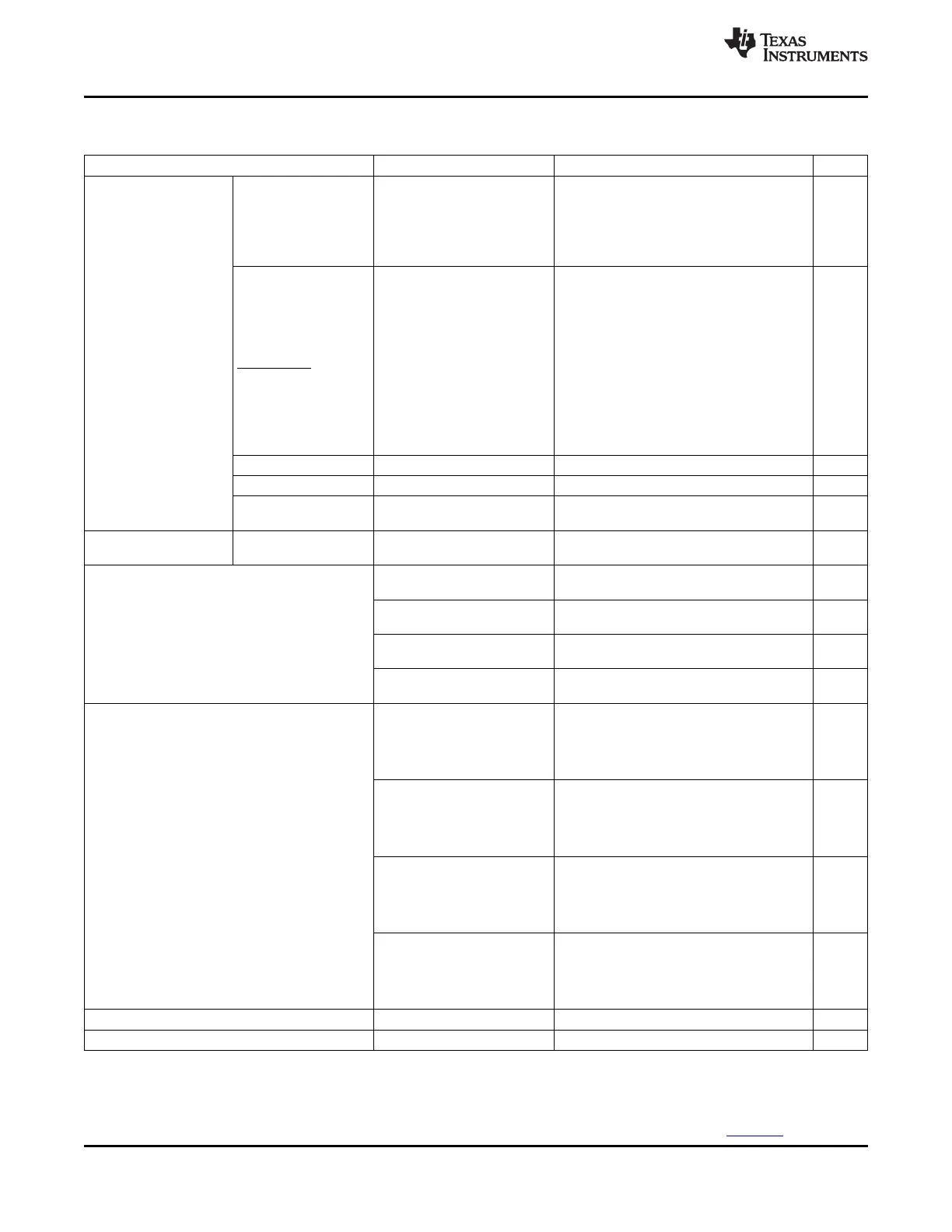
Electrical Characteristics Over Recommended Ranges of Supply Voltage and Operating Case
Temperature (Unless Otherwise Noted) (continued)
PARAMETER TEST CONDITIONS
(1)
MIN TYP MAX UNIT
AECLKOUT,
CLKR1/GP[0],
CLKX1/GP[3],
8 mA
SYSCLK4/GP[1],
EMU[18:0], CLKR0,
CLKX0
EMIF pins (except
AECLKOUT), NMI,
TOUT0L, TINP0L,
TOUTP1L, TINP1L,
PCI_EN, EMAC-
Low-level output
capable pins (except
I
OL
current [DC]
RGMII pins), 4 mA
RESETSTAT, McBSP-
capable pins (except
CLKR1/GP[0],
CLKX1/GP[3], CLKR0,
CLKX0), GP[7:4], and
TDO
PCI-capable pins
(2)
1.5 mA
RGMII pins 8 mA
DDR2 memory
-4 mA
controller pins
Off-state output
I
OZ
(5)
3.3-V pins V
O
= DV
DD33
or 0 V -20 20 uA
current [DC]
CV
DD
= 1.25 V,
1.76 W
CPU frequency = 1200 MHz
CV
DD
= 1.25 V,
1.66 W
CPU frequency = 1000 MHz
P
CDD
Core supply power
(6)
CV
DD
= 1.2 V,
1.41 W
CPU frequency = 850 MHz
CV
DD
= 1.2 V,
1.29 W
CPU frequency = 720 MHz
DV
DD33
= 3.3 V,
DV
DD18
= DV
DDR
= 1.8 V,
PLLV1 = PLLV2 = AV
DLL1
= 0.54 W
AV
DLL2
= 1.8 V,
CPU frequency = 1200 MHz
DV
DD33
= 3.3 V,
DV
DD18
= DV
DDR
= 1.8 V,
PLLV1 = PLLV2 = AV
DLL1
= 0.53 W
AV
DLL2
= 1.8 V,
CPU frequency = 1000 MHz
P
DDD
I/O supply power
(6)
DV
DD33
= 3.3 V,
DV
DD18
= DV
DDR
= 1.8 V,
PLLV1 = PLLV2 = AV
DLL1
= 0.53 W
AV
DLL2
= 1.8 V,
CPU frequency = 850 MHz
DV
DD33
= 3.3 V,
DV
DD18
= DV
DDR
= 1.8 V,
PLLV1 = PLLV2 = AV
DLL1
= 0.52 W
AV
DLL2
= 1.8 V,
CPU frequency = 720 MHz
C
i
Input capacitance 10 pF
C
o
Output capacitance 10 pF
(5) I
OZ
applies to output-only pins, indicating off-state (hi-Z) output leakage current.
(6) Assumes the following conditions: 60% CPU utilization; DDR2 at 50% utilization (250 MHz), 50% writes, 32 bits, 50% bit switching; two
2-MHz McBSPs at 100% utilization, 50% switching; two 75-MHz Timers at 100% utilization; device configured for HPI32 mode with pull-
up resistors on HPI pins; room temperature (25°C). The actual current draw is highly application-dependent. For more details on core
and I/O activity, see the TMS320C6455/54 Power Consumption Summary application report (literature number SPRAAE8).
100 Device Operating Conditions Copyright © 2005–2012, Texas Instruments Incorporated
Submit Documentation Feedback
Product Folder Link(s): TMS320C6455