TMS320C6455
SPRS276M –MAY 2005–REVISED MARCH 2012
www.ti.com
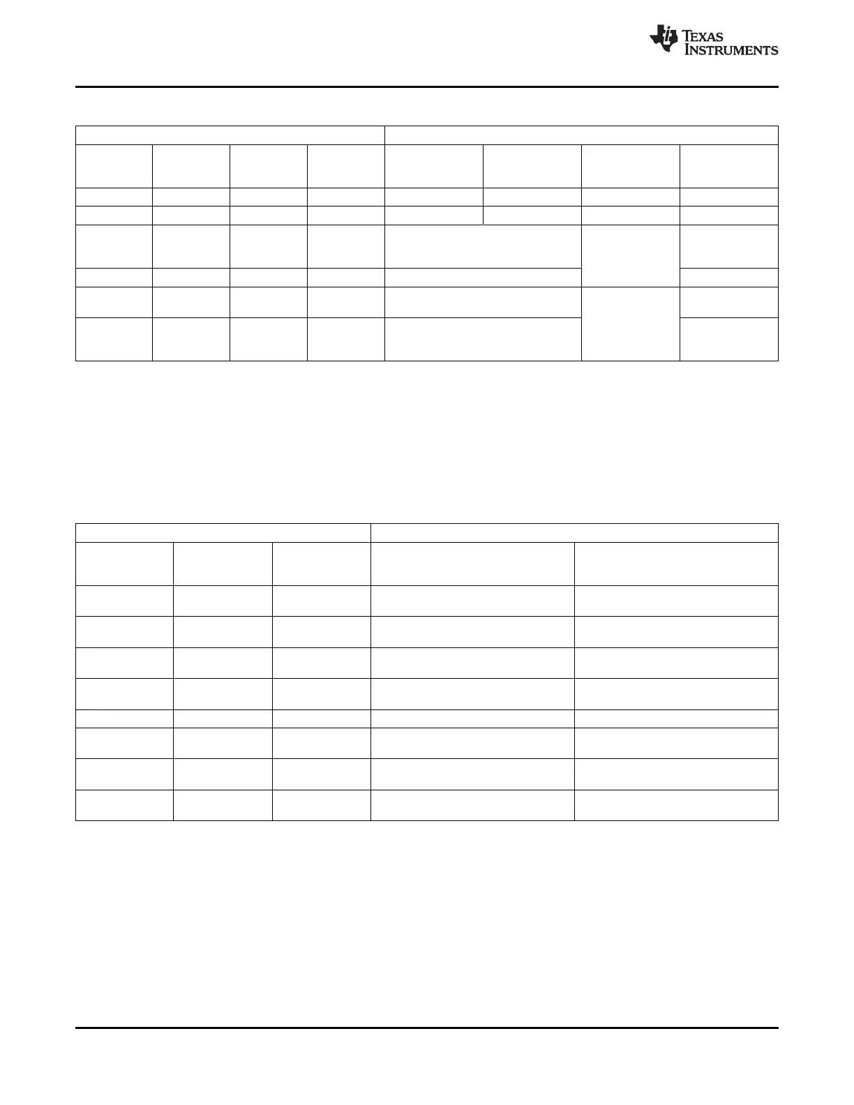
Table 3-2. PCI_EN, PCI66, PCI_EEAI, and HPI_WIDTH Peripheral Selection (HPI and PCI)
CONFIGURATION PIN SETTING
(1)
PERIPHERAL FUNCTION SELECTED
PCI66 PCI_EEAI HPI_WIDTH
PCI_EN PIN HPI DATA HPI DATA 32-BIT PCI PCI
AEA6 PIN AEA8 PIN AEA14 PIN
[Y29] LOWER UPPER (66-/33-MHz) AUTO-INIT
[U27] [P25]
(1)
[R25]
0 0 0 0 Enabled Hi-Z Disabled N/A
0 0 0 1 Enabled Enabled Disabled N/A
Enabled
1 1 1 X Disabled (via External I2C
Enabled
EEPROM)
(66 MHz)
1 1 0 X Disabled Disabled
Disabled
1 0 0 X Disabled
(default values)
Enabled
Enabled
(33 MHz)
1 0 1 X Disabled (via External I2C
EEPROM)
(1) PCI_EEAI is latched at reset as a configuration input. If PCI_EEAI is set as one, then default values are loaded from an external I2C
EEPROM.
The UTOPIA and EMAC/MDIO pins are also multiplexed on the TCI6482 device. The UTOPIA_EN
function (AEA12 pin) controls the function of these multiplexed pins. The MAC_SEL[1:0] configuration pins
(AEA[10:9) control which interface is used by the EMAC/MDIO. Note that since the PCI shares some pins
with the UTOPIA peripheral, its state also affects the operation of the UTOPIA. Table 3-3 describes the
effect of the UTOPIA_EN, PCI_EN, and MACSEL[1:0] configuration pins.
Table 3-3. UTOPIA_EN, and MAC_SEL[1:0] Peripheral Selection (UTOPIA and EMAC)
CONFIGURATION PIN SETTING PERIPHERAL FUNCTION SELECTED
MAC_SEL[1:0]
UTOPIA_EN PCI_EN PIN
AEA[10:9] PINS EMAC/MDIO UTOPIA
AEA12 PIN [R28] [Y29]
[M25, M27]
10/100 EMAC/MDIO with MII Interface
0 x 00b Disabled
[default]
10/100 EMAC/MDIO with RMII
0 x 01b Disabled
Interface
10/100/1000 EMAC/MDIO with GMII
0 x 10b Disabled
Interface
10/100/1000 EMAC/MDIO with RGMII
0 x 11b Disabled
Interface
(1)
1 0 00b, 01b, or 10b Disabled UTOPIA Slave with Full Functionality
10/100/1000 EMAC/MDIO with RGMII
1 0 11b UTOPIA Slave with Full Functionality
Interface
(1)
UTOPIA Slave with Single PHY Mode
1 1 00b, 01b, or 10b Disabled
Only
10/100/1000 EMAC/MDIO with RGMII UTOPIA Slave with Single PHY Mode
1 1 11b
Interface
(1)
Only
(1) RGMII interface requires a 1.5-/1.8-V I/O supply.
3.3 Peripheral Selection After Device Reset
On the C6455 device, peripherals can be in one of several states. These states are listed in Table 3-4.
58 Device Configuration Copyright © 2005–2012, Texas Instruments Incorporated
Submit Documentation Feedback
Product Folder Link(s): TMS320C6455