TRST
IEEE Standard
1149.1
(JTAG)
Emulation
Reserved
Reset and
Interrupts
Control/Status
TDI
TDO
TMS
TCK
NMI
RESET
RSV03
RSV04
Clock/PLL1
and
PLL Controller
CLKIN1
EMU0
EMU1
SYSCLK4/GP[1]
(A)
EMU14
EMU15
EMU16
EMU17
RSV02
EMU18
RSV07
RSV09
RSV05
RSV43
RSV44
RSV42
•
•
•
•
•
•
RESETSTAT
CLKIN2
POR
PCI_EN
Peripheral
Enable/Disable
Clock/PLL2
PLLV2
PLLV1
TMS320C6455
SPRS276M –MAY 2005–REVISED MARCH 2012
www.ti.com
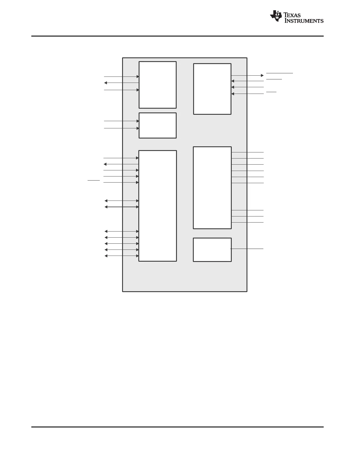
2.6 Signal Groups Description
A. This pin functions as GP[1] by default. For more details, see Section 3.
Figure 2-6. CPU and Peripheral Signals
20 Device Overview Copyright © 2005–2012, Texas Instruments Incorporated
Submit Documentation Feedback
Product Folder Link(s): TMS320C6455