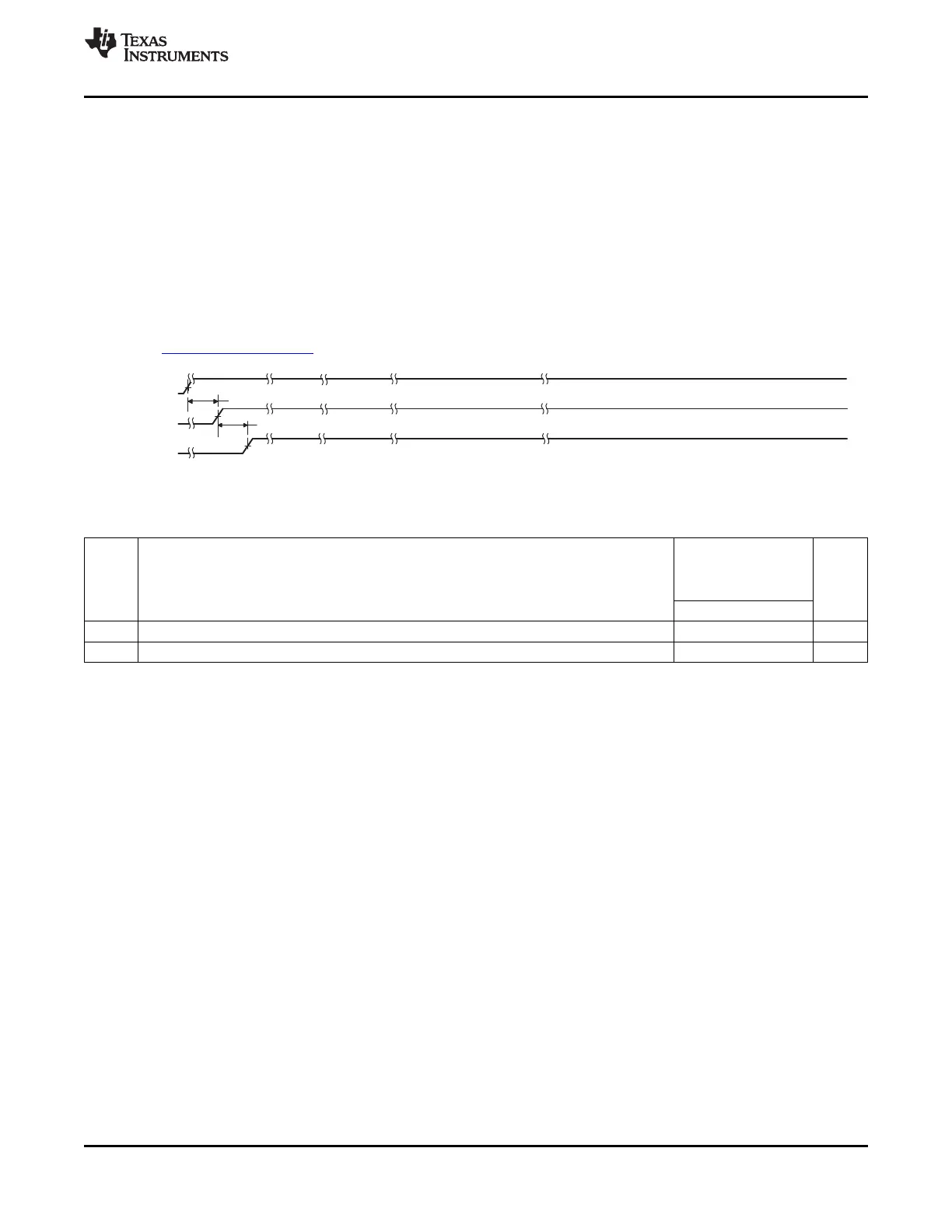
DV
DD33
CV
DD12
All other
power supplies
1
2
TMS320C6455
www.ti.com
SPRS276M –MAY 2005–REVISED MARCH 2012
7.2 Recommended Clock and Control Signal Transition Behavior
All clocks and control signals must transition between V
IH
and V
IL
(or between V
IL
and V
IH
) in a monotonic
manner.
7.3 Power Supplies
7.3.1 Power-Supply Sequencing
TI recommends the power-supply sequence shown in Figure 7-5. After the DV
DD33
supply is stable, the
remaining power supplies can be powered up at the same time as CV
DD
as long as their supply voltage
never exceeds the CV
DD
voltage during powerup. Some TI power-supply devices include features that
facilitate power sequencing; for example, Auto-Track or Slow-Start/Enable features. For more information,
visit www.ti.com/dsppower.
Figure 7-5. Power-Supply Sequence
Table 7-2. Timing Requirements for Power-Supply Sequence
-720
-850
A-1000/-1000
NO. UNIT
-1200
MIN MAX
1 t
su(DVDD33-CVDD12)
Setup time, DV
DD33
supply stable before CV
DD12
supply stable 0.5 200 ms
2 t
su(CVDD12-ALLSUP)
Setup time, CV
DD12
supply stable before all other supplies stable 0 200 ms
7.3.2 Power-Supply Decoupling
In order to properly decouple the supply planes from system noise, place as many capacitors (caps) as
possible close to the DSP. These caps need to be close to the DSP, no more than 1.25 cm maximum
distance to be effective. Physically smaller caps are better, such as 0402, but need to be evaluated from a
yield/manufacturing point-of-view. Parasitic inductance limits the effectiveness of the decoupling
capacitors, therefore physically smaller capacitors should be used while maintaining the largest available
capacitance value. As with the selection of any component, verification of capacitor availability over the
product's production lifetime should be considered.
7.3.3 Power-Down Operation
One of the power goals for the C6455 device is to reduce power dissipation due to unused peripherals.
There are different ways to power down peripherals on the C6455 device.
Some peripherals can be statically powered down at device reset through the device configuration pins
(see Section 3.1, Device Configuration at Device Reset). Once in a static power-down state, the peripheral
is held in reset and its clock is turned off. Peripherals cannot be enabled once they are in a static power-
down state. To take a peripheral out of the static power-down state, a device reset must be executed with
a different configuration pin setting.
After device reset, all peripherals on the C6455 device are in a disabled state and must be enabled by
software before being used. It is possible to enable only the peripherals needed by the application while
keeping the rest disabled. Note that peripherals in a disabled state are held in reset with their clocks
gated. For more information on how to enable peripherals, see Section 3.3, Peripheral Selection After
Device Reset.
Copyright © 2005–2012, Texas Instruments Incorporated C64x+ Peripheral Information and Electrical Specifications 103
Submit Documentation Feedback
Product Folder Link(s): TMS320C6455