TMS320C6455
SPRS276M –MAY 2005–REVISED MARCH 2012
www.ti.com
7.10.3.2 Programmable Synchronous Interface Timing
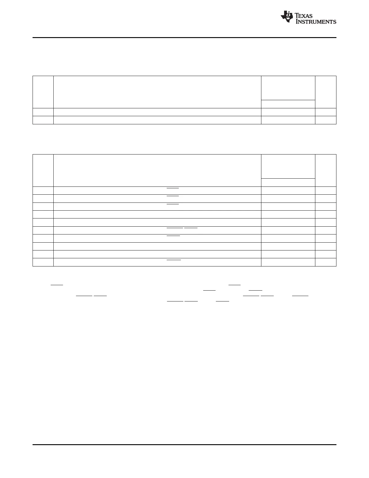
Table 7-46. Timing Requirements for Programmable Synchronous Interface Cycles for EMIFA Module
(see Figure 7-36)
-720
-850
A-1000/-1000
NO. UNIT
-1200
MIN MAX
6 t
su(EDV-EKOH)
Setup time, read AEDx valid before AECLKOUT high 2 ns
7 t
h(EKOH-EDV)
Hold time, read AEDx valid after AECLKOUT high 1.5 ns
Table 7-47. Switching Characteristics Over Recommended Operating Conditions for Programmable
Synchronous Interface Cycles for EMIFA Module
(1)
(see Figure 7-36 through Figure 7-38)
-720
-850
A-1000/-1000
NO. PARAMETER UNIT
-1200
MIN MAX
1 t
d(EKOH-CEV)
Delay time, AECLKOUT high to ACEx valid 1.3 4.9 ns
2 t
d(EKOH-BEV)
Delay time, AECLKOUT high to ABEx valid 4.9 ns
3 t
d(EKOH-BEIV)
Delay time, AECLKOUT high to ABEx invalid 1.3 ns
4 t
d(EKOH-EAV)
Delay time, AECLKOUT high to AEAx valid 4.9 ns
5 t
d(EKOH-EAIV)
Delay time, AECLKOUT high to AEAx invalid 1.3 ns
8 t
d(EKOH-ADSV)
Delay time, AECLKOUT high to ASADS/ASRE valid 1.3 4.9 ns
9 t
d(EKOH-OEV)
Delay time, AECLKOUT high to ASOE valid 1.3 4.9 ns
10 t
d(EKOH-EDV)
Delay time, AECLKOUT high to AEDx valid 4.9 ns
11 t
d(EKOH-EDIV)
Delay time, AECLKOUT high to AEDx invalid 1.3 ns
12 t
d(EKOH-WEV)
Delay time, AECLKOUT high to ASWE valid 1.3 4.9 ns
(1) The following parameters are programmable via the EMIFA CE Configuration registers (CEnCFG):
• Read latency (R_LTNCY): 0-, 1-, 2-, or 3-cycle read latency
• Write latency (W_LTNCY): 0-, 1-, 2-, or 3-cycle write latency
• ACEx assertion length (CE_EXT): For standard SBSRAM or ZBT SRAM interface, ACEx goes inactive after the final command has
been issued (CE_EXT = 0). For synchronous FIFO interface with glue, ACEx is active when ASOE is active (CE_EXT = 1).
• Function of ASADS/ASRE (R_ENABLE): For standard SBSRAM or ZBT SRAM interface, ASADS/ASRE acts as ASADS with
deselect cycles (R_ENABLE = 0). For FIFO interface, ASADS/ASRE acts as ASRE with NO deselect cycles (R_ENABLE = 1).
164 C64x+ Peripheral Information and Electrical Specifications Copyright © 2005–2012, Texas Instruments Incorporated
Submit Documentation Feedback
Product Folder Link(s): TMS320C6455