TMS320C6455
www.ti.com
SPRS276M –MAY 2005–REVISED MARCH 2012
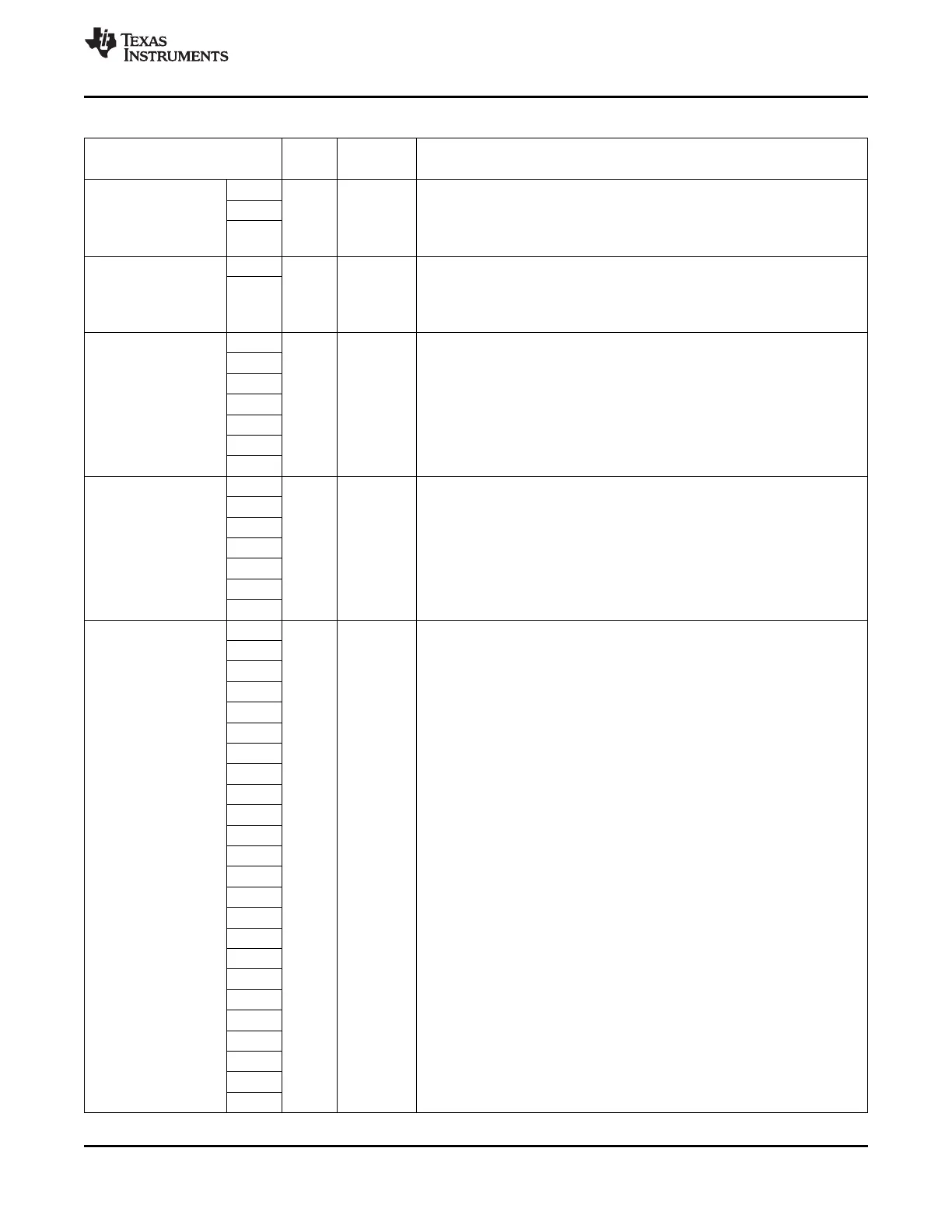
Table 2-3. Terminal Functions (continued)
SIGNAL
TYPE
(1)
IPD/IPU
(2)
DESCRIPTION
NAME NO.
U16 SRIO interface supply:
1.25-V core supply voltage (-1000 and -1200 devices)
V15
DV
DDRM
S 1.2-V core supply voltage (-850 devices).
The source for this supply voltage must be the same as that of CV
DD
.
V17
NOTE: If RapidIO is not used, these pins can be connected directly to V
SS
.
W16 Main SRIO supply:
1.25-V I/O supply voltage (-1000 and -1200 devices)
DV
DD12
S 1.2-V I/O supply voltage (-850 devices).
W18
Do not use core supply.
NOTE: If RapidIO is not used, these pins can be connected directly to V
SS
.
AE17
AE19
SRIO termination supply:
AE23
1.25-V I/O supply voltage (-1000 and -1200 devices)
AV
DDT
AF20 A 1.2-V I/O supply voltage (-850 devices).
Do not use core supply.
AH20
NOTE: If RapidIO is not used, these pins can be connected directly to V
SS
.
AJ17
AJ23
A1
B5
1.8-V or 1.5-V I/O supply voltage for the RGMII function of the EMAC.
NOTE: If the RGMII mode of the EMAC is not used, the DV
DD15
, V
REFHSTL
,
D2
RSV13, and RSV14 pins can be connected to directly ground (V
SS
) to save
DV
DD15
D5 S
power. However, connecting these pins directly to ground will prevent
F5
boundary-scan from functioning on the RGMII pins of the EMAC. To preserve
boundary-scan functionality on the RGMII pins, see Section 7.3.4.
G6
H7
B8
B11
B20
B23
E10
E12
E22
E24
F7
F11
F13
F15
DV
DD18
S 1.8-V I/O supply voltage (DDR2 Memory Controller)
F17
F19
F23
G8
G10
G12
G14
G16
G18
G20
G22
G24
Copyright © 2005–2012, Texas Instruments Incorporated Device Overview 43
Submit Documentation Feedback
Product Folder Link(s): TMS320C6455