C H A P T E R 7 – T E S T S A N D T E S T C O N D I T I O N S
AT5600 User Manual 98-119 issue 14 Page 107
7.11. LL - Leakage Inductance
Where Used
Leakage inductance is important in many applications. One example is fly-back
designs for high frequency switched mode power supplies, where the leakage
inductance must be less than a specified critical value for proper operation.
Measurement Conditions
Leakage inductance is tested by measuring the inductance of a 'primary' winding
when one or more 'secondary' windings are shorted out. In performing the
calculation at the end of the test to extract the inductance value from the
measured winding impedance, the tester uses a series equivalent circuit.
In making the measurement, the tester automatically compensates for the
impedance of the wiring, the connections and the relays in the shorting path.
Leakage inductance can be measured using a test current in the range 20A to
100mA at a frequency of 20Hz to 3MHz.
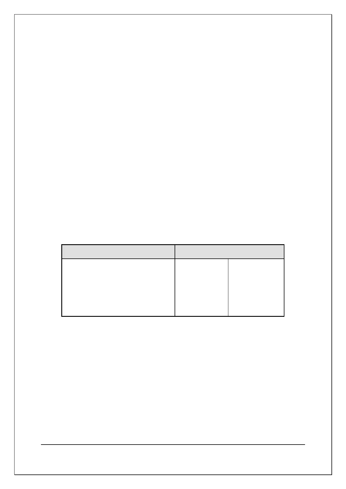
You may choose a suitable test current and frequency based on the expected
value of the leakage inductance using the following table:
Table 2
The Test Conditions for Leakage Inductance Measurement
NOTE: Because leakage inductance is measured with a secondary winding
shorted out, be careful to choose a test signal that will not cause excessive
currents to flow. This is particularly significant in transformers where the turns
ratio is very high, and the shorted winding has only a few turns.
If, for example, the primary winding has 300 turns, and the secondary 3 turns, a
test current of 10mA flowing through the leakage inductance on the primary side
will give rise to a current of 1 Amp flowing in the shorted secondary winding.
To protect transformer windings, the test current when measuring leakage
inductance is limited in the table to 50mA maximum.