C H A P T E R 8 – F R O N T P A N E L O P E R A T I O N
AT5600 User Manual 98-119 issue 14 Page 193
8.2. Testing Wound Components
8.2.1. A Typical Workflow
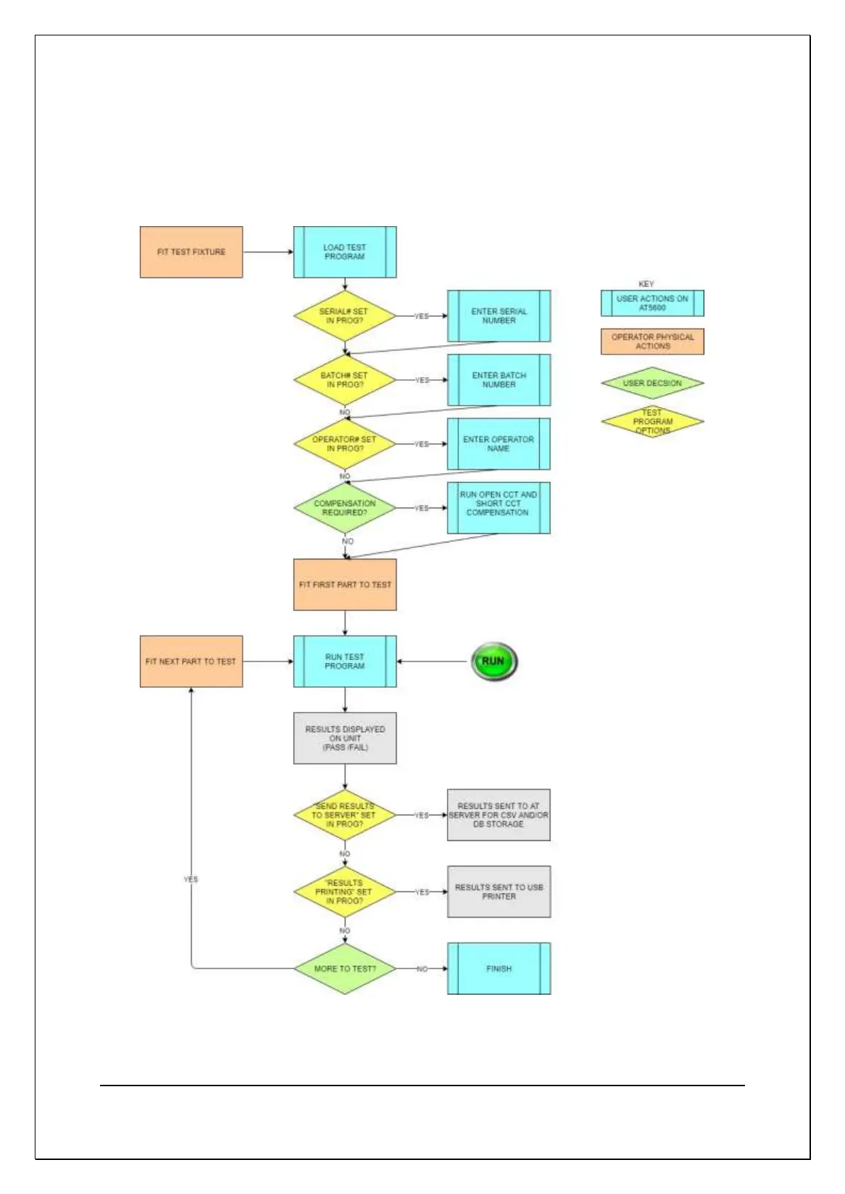
The below shows the basic test execution flow, and the possible sequence of user inputs
(set in the AT EDITOR program options) during testing.