C H A P T E R 1 4 - A T E D I T OR
AT5600 User Manual 98-119 issue 14 Page 335
14.6.14. C2 – Capacitance Match
The Interwinding capacitance match test calculates the ratio between two
capacitance measurements on two groups of windings. It is measured by
applying a specified AC voltage between two separate windings and the voltage
across and current flow between the two windings is measured to obtain a
complex impedance. This is performed to the two groups in turn.
This test is suitable for switched mode power supply, audio and
telecommunication transformers. It checks that the windings are installed in the
correct positions on the bobbin.
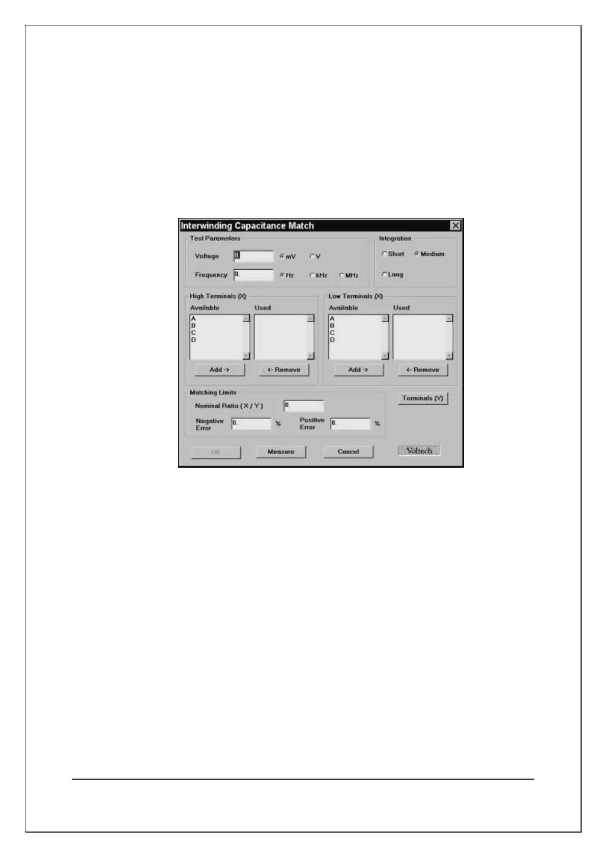
On selecting "C2 Interwinding Capacitance Match" from the available tests
window, a dialogue box will be displayed.
To program the test:
1. Enter the voltage and frequency required for the test.
(Refer to Chapter 7 - ‘Test Conditions’, which lists recommended test
conditions for different values of capacitance.)
2. Select the integration time you require.
'Medium' is the default setting. 'Long' will give more stable readings (for
tighter limits) at the expense of an increased test time, and 'Short' will test
at the maximum speed, but may give a slightly noisier reading. See 7.3
Explanation of Integration.
3. Select the terminals to be included for both high and low X test terminals.
4. Selecting Terminals [Y] prompts a second dialogue box allowing the second
set of windings to be configured for the test.
5. Set the capacitance limits.
Note: The Measure button may be used here as outlined in section 14.5.9.