C H A P T E R 10 – S P E C I F I C A T I O N S
AT5600 User Manual 98-119 issue 14 Page 242
10.3.3. Remote Port
TTL compatible interface for operation with various peripherals including foot
switch, remote controller and monitor output.
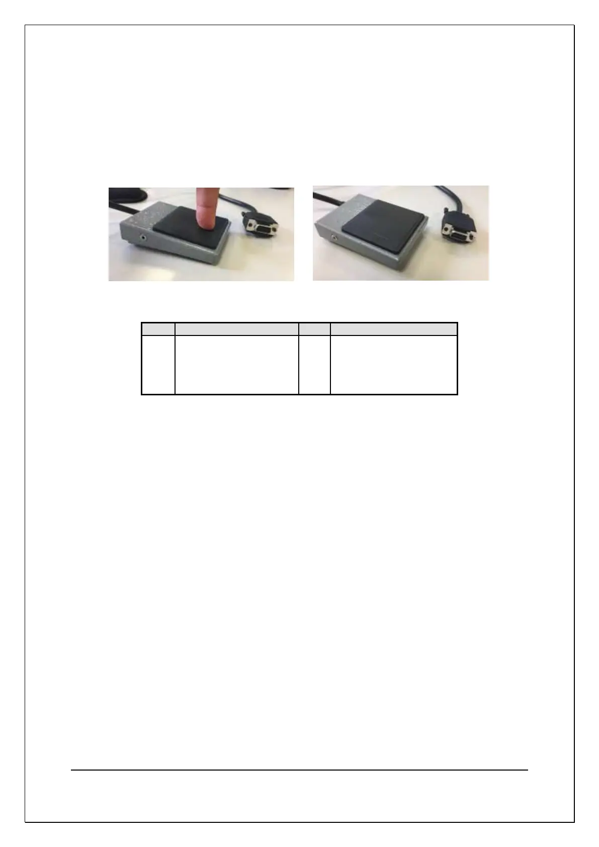
The Voltech footswitch (Part Number 91-058) can be purchased form Voltech
and plugs into the remote port. This gives a simple foot pedal to trigger RUN on
the AT5600 (also compatible with AT3600)
9-pin male D-type connector
Signals with a name starting with ! are active Lo.
!RUN Input (Pin 3)
The !RUN input is an active Lo input with an internal pull-up resistor. In the
execution of programs, it is equivalent to pressing the RUN key on the front panel.
To use this with a foot-switch, wire the switch between this input and 0V.
!STOP Input (Pin 9)
The !STOP input is an active Lo input with an internal pull-up resistor.
The active-going edge of this input halts all AT5600 activity, turning off all signal
sources.
To use this with an ‘emergency stop’ switch, wire the switch between this input
and 0V.
Status Outputs (Pins 2, 4 and 6)
The status outputs are standard 5 Volt logic signals.