C H A P T E R 10 – S P E C I F I C A T I O N S
AT5600 User Manual 98-119 issue 14 Page 246
10.3.6. User Port
The User Port is positioned on the rear panel of the AT5600 and contains six
open-collector relay drive outputs, and two HC MOS compatible inputs.
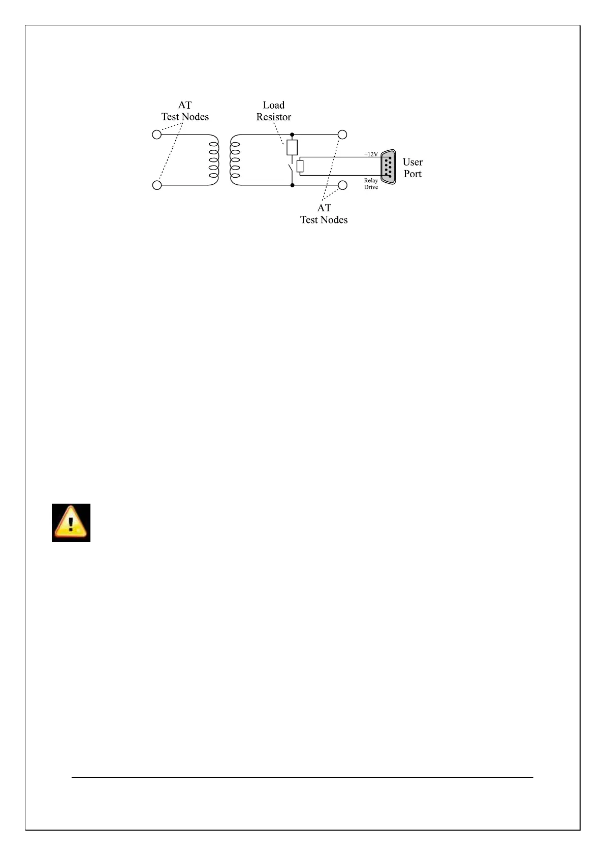
The relay drives are switched on and off by the OUT test, inserted into your test
program sequence. This will enable you, for example, to switch a dummy load on
to the secondary winding of the transformer under test, so that subsequent tests
are performed on the loaded transformer.
The OUT test switches the control lines to the programmed levels in the following
manner;
1 Open any relays changing to OFF
2 Wait 20mSecs
3 Close any relays switching to ON
4 Wait 20msecs
5 proceeds to the next test.
BEWARE OF HIGH VOLTAGES
Remember when designing relays into your fixture that the AT5600 can produce
very high voltages.
It is the responsibility of the user to ensure that both the relays themselves and
the associated wiring can withstand any high voltage produced in the test
program.
It is particularly important that YOU ensure that there is never a flash-over from a
high voltage test signal to a relay coil driven from the User Port. Such a flash-
over would cause extensive damage to the circuits inside the AT5600.
If in any doubt, contact your Voltech supplier for advice on which relay to use in
your application.