C H A P T E R 6 – S A F E T Y S Y S T E M S
AT5600 User Manual 98-119 issue 14 Page 83
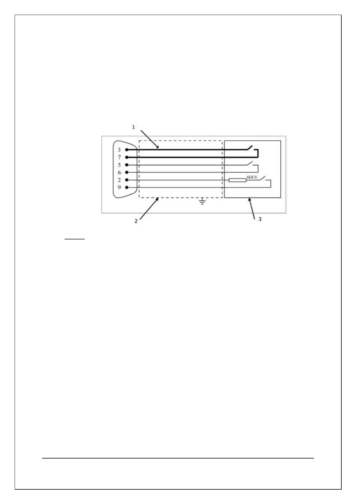
6.2.3. Constructing your own Safety System
Figure 6.2.3 shows the principles of how to construct a safety system based on
the signals available on the 9-way AT Safety Interlock connector.
For the interlock to be activated three separate conditions must be met. One of
the conditions is a fixed resistor which prevents accidental activation if all pins on
the AT5600 are shorted together.
Notes:
1) The connection between pins 3 and 7 must be made with cable rated at
400V / 1A RMS or higher.
2) The Safety signal cables and Safety relay must be protected from damage
inside a covering which is earth bonded.
3) The safety signals may be switched using Safety electromechanical relays,
contactors, or any other switches operated by a device that detects an
operator has breached the safety barrier(s).
Voltech can supply a pre-made cable suitable for integrating the AT with your
own system
Part number 250-030 Safety Interlock Cable
User manual 98-121 Safety Interlock Cable User Manual