C H A P T E R 5 – G E T T I N G S T A R T E D
AT5600 User Manual 98-119 issue 14 Page 64
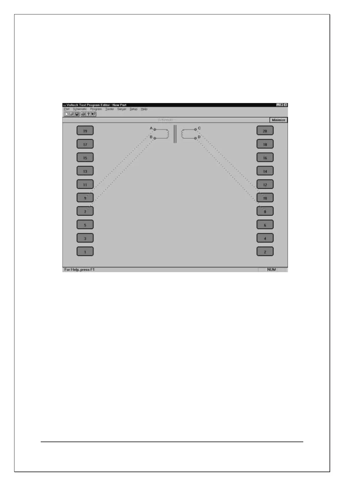
Now, connect the windings to the test nodes of the tester:
Place the mouse pointer over terminal A; press and hold the right mouse button.
Continue holding the mouse button down and drag the mouse pointer to test node
9. Release the button. A wire will now connect terminal A to test node 9. Repeat
this procedure to connect the other three terminals, B, C and D to nodes 7, 10
and 8. The screen should now look like this:
You have now created a schematic layout of a four-terminal transformer.
5.4.2. Creating the Test Program
After creating the transformer schematic, you may now create an example
program, containing the following four tests:
Resistance of winding AB (1 M to 209 m)
Resistance of winding CD (171 m to 209 m)
Inductance of winding AB (>330 uH)
Turns ratio AB to CD (1:1 2%)