C H A P T E R 1 4 - A T E D I T OR
AT5600 User Manual 98-119 issue 14 Page 320
14.6.6. QL - Quality Factor
To test for Q factor, an AC voltage is applied across the selected winding. The
voltage across and current through the winding are then measured using
harmonic analysis. The measured voltage is divided by the current to obtain a
complex impedance, from which the Q factor is calculated.
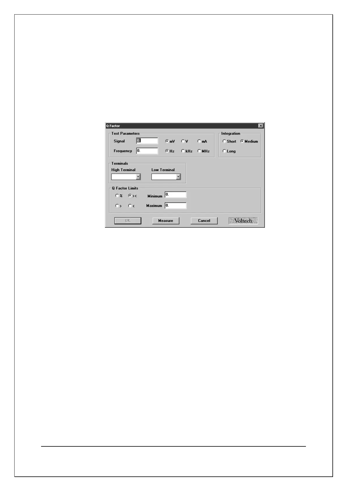
On selecting ‘QL Q Factor’ from the Available Tests window, a dialogue box will
be displayed.
To program the test:
1. Enter the signal and frequency required for the test.
Note that the signal is normally entered as a voltage by selecting the 'mV'
or 'V' button; but you may optionally enter it as a current by selecting the
'mA' button.
(If in doubt, refer to Chapter 7 - ‘Test Conditions’, which lists
recommended test conditions based on the values of winding inductance).
Normally, the Q factor test would follow an inductance test on the same
winding. Using the same test conditions for both tests will speed the
execution of the program.
2. Select (mouse click the button) the integration time you require.
'Medium' is the default setting. 'Long' will give more stable readings (for tighter
limits) at the expense of an increased test time, and 'Short' will test at the
maximum speed, but may give a slightly noisier reading. See 7.3 Explanation
of Integration.
3. Enter the high and low terminal names. Use the mouse to pull down the
menu along side the fill-in box, and double click to select the terminal.
4. Select (mouse click the button) the type of limits you require and enter the
values.
% Enter a nominal value and then the limits as negative and
positive