C H A P T E R 1 4 - A T E D I T OR
AT5600 User Manual 98-119 issue 14 Page 274
14.4. Schematic Editing
The first step in creating a test program is to draw a schematic diagram. This tell
the Editor software which test nodes will be used to make electrical connections
to the part under test and allows error checking to be performed when
programming the tests. A schematic is also a great visual reference while creating
the test program.
This section covers how to:
• Create or add a transformer winding
• Connect the winding terminals to test nodes
• Delete a winding
• Rename a terminal
• Add a terminal
• Delete a terminal
• Add a core connection
• Delete a core connection
• Add a screen connection
• Delete a screen connection
14.4.1. Adding a Transformer Winding
To add a transformer winding onto the screen:
1. Select ‘Add Winding’ from the Schematic menu on the menu bar.
2. Place the winding on the screen:
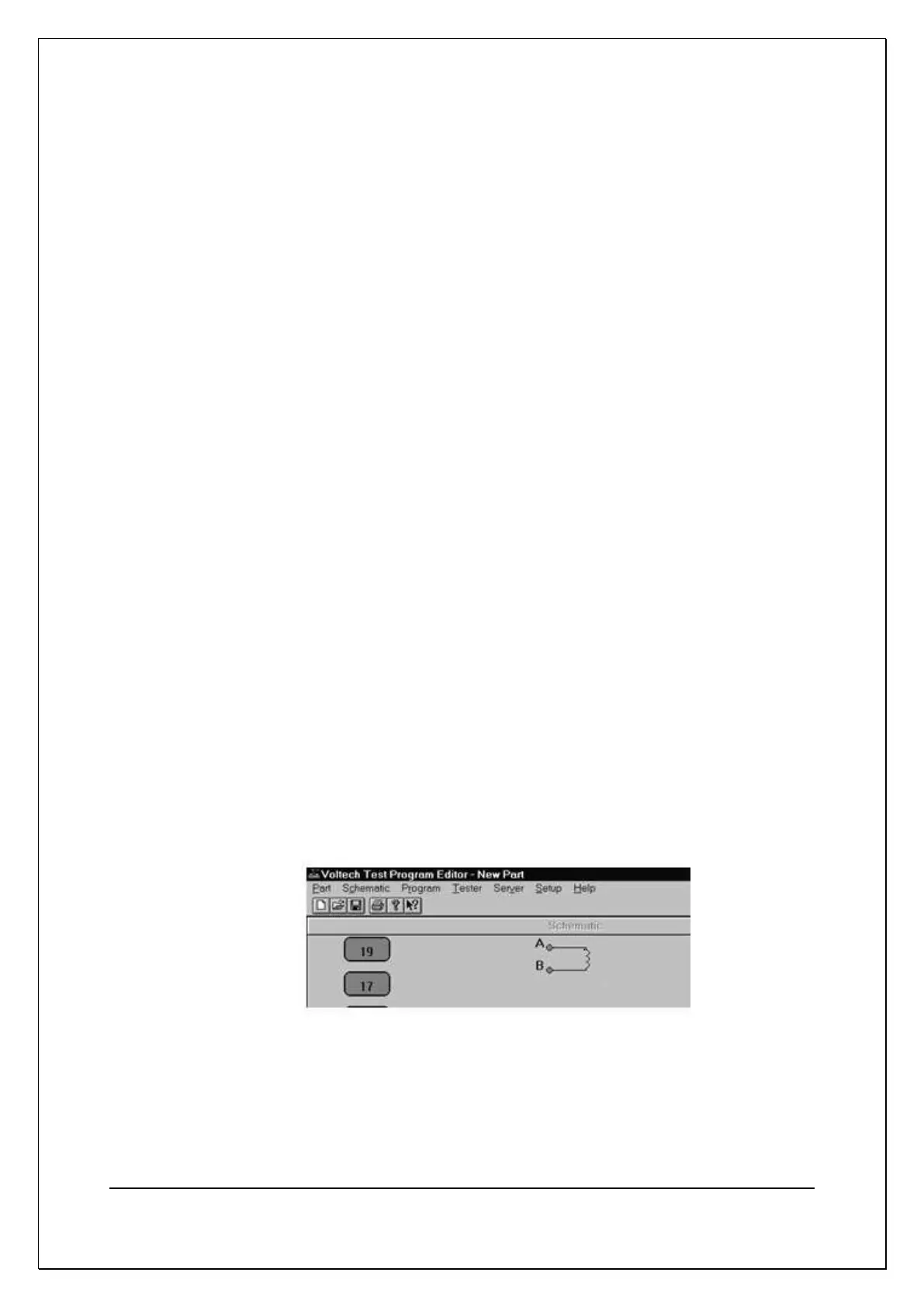
A winding will now be displayed attached to the mouse pointer on the screen.
You must decide which half of the screen to place the winding. On crossing
the mid-point of the screen, the winding is mirrored to face the nearest test
nodes. Click the left mouse button to place the winding.
3. When the winding is placed, a dialogue box appears prompting you to name
both of the winding’s two terminals.