C H A P T E R 2 – S Y S T E M O V E R V I E W
AT5600 User Manual 98-119 issue 14 Page 38
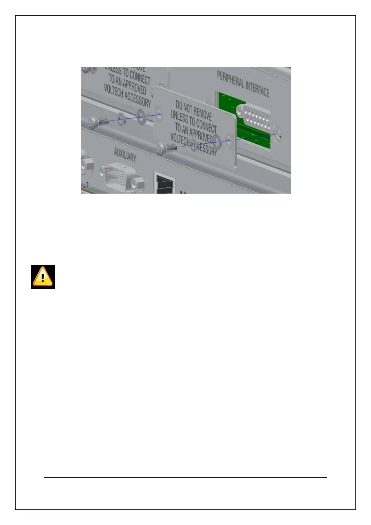
Removal and Replacement of a Cover Plate
(4) Remote Port
The Remote Port is used to electrically signal the status and control the AT5600
allowing external indicators (Running/Pass/Fail) and control inputs (Run/Stop).
For more information see 10.3.3
(5) Chassis Terminal (0V)
This is the AT5600 chassis 0V potential and it used when connecting peripherals
that need to reference the signal potentials. It is a 4mm Banana socket
connection. THIS SOCKET IS NOT TO BE USED TO EARTH THE AT5600.
(6) User Port
The User Port provides open collector style outputs that are used as
electronic switches for control of additional relays and other devices. For more
information see 10.3.6 and 7.26
(7) Rear USB ‘A’ connector and Ethernet Port
This allows printing of test results to a USB Epson TM-T88V Printer.
The Ethernet Port provides a 10/100 Ethernet Network connection for
communication with the AT5600 using the TCP/IP protocol. This is the
recommended method for communication with the Voltech AT Series Server
Software.
(8) Auxiliary Port
This RS232 serial port is used for connection to external peripherals or a
computer system running the Voltech AT Series Editor software.