5.8 L: Protection Functions
YASKAWA ELECTRIC SIEP C710616 35D YASKAWA AC Drive E1000 Technical Manual 211
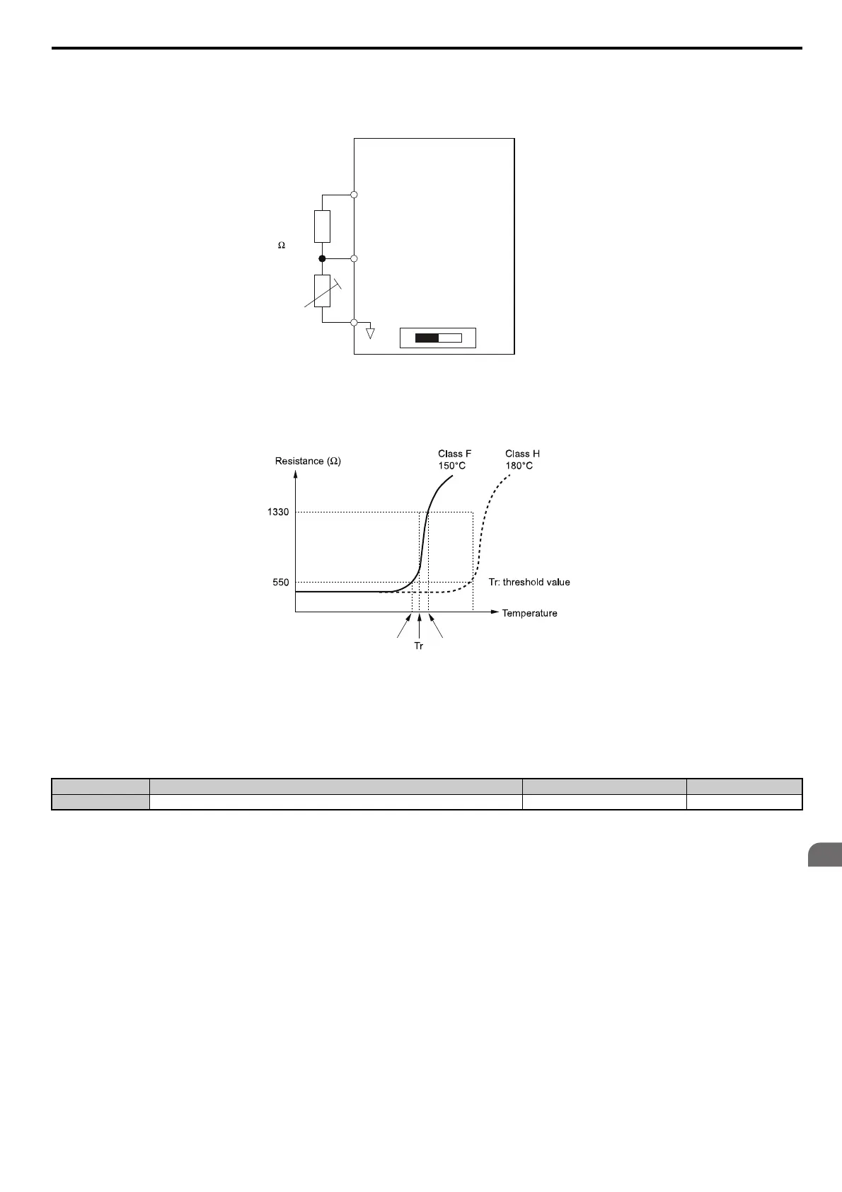
Figure 5.62 shows a PTC connection example for analog input A2. If using analog input A2, make sure to set DIP switch
S1 on the terminal board for voltage input when using this function.
Figure 5.62
Figure 5.62 Connection of a Motor PTC
The PTC must have the following characteristics for one motor phase. The drives motor overload detection expects 3 of
these PTCs to be connected in series.
Figure 5.63
Figure 5.63 Motor PTC Characteristics
Overheat detection using a PTC can be set up by parameters L1-03, L1-04, and L1-05 as explained below.
■
L1-03: Motor Overheat Alarm Operation Selection (PTC input)
Sets the drive operation when the PTC input signal reaches the motor overheat alarm level (oH3).
Setting 0: Ramp to stop
The drive stops the motor using the deceleration time 1 set in parameter C1-02.
Setting 1: Coast to stop
The drive output is switched off and the motor coasts to stop.
Setting 2: Fast Stop
The drive stops the motor using the Fast Stop time set in parameter C1-09.
Setting 3: Alarm only
The operation is continued and an oH3 alarm is displayed on the digital operator.
No. Name Setting Range Default
L1-03 Motor Overheat Alarm Operation Selection (PTC input) 0 to 3 3
Drive
+V
(+10.5V, 20 mA)
Branch
resistor
12 k
PTC
thermistor
A2 (0-10 V)
AC
DIP switch S1
VI
Tr’
Tr + 5K (oH4 Fault Level)Tr - 5K (oH3 Alarm Level)
SIEP_C710616_35.book 211 ページ 2015年11月30日 月曜日 午後2時2分