5.8 L: Protection Functions
218 YASKAWA ELECTRIC SIEP C710616 35D YASKAWA AC Drive E1000 Technical Manual
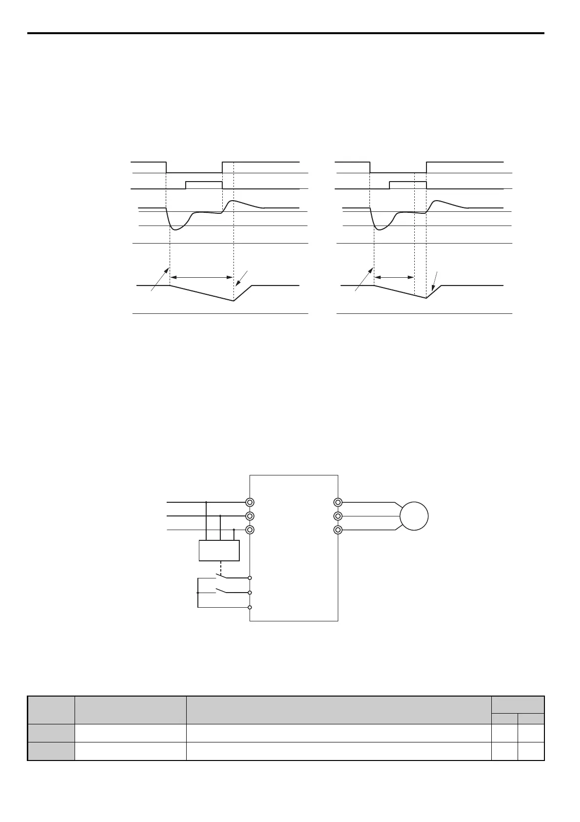
KEB Ride-Thru Operation as Long as CPU Has Power, KEB Input Used
Here, L2-01 = 3 and an input terminal is set to issue KEB Ride-Thru (H1- = 65, 66, 7A, 7B). After decelerating for
the time set in parameter L2-10, the drive checks the DC bus voltage and the status of the digital input. If the DC bus
voltage is still below the level set in L2-11 or if the digital input assigned to KEB Ride-Thru is still active, then the drive
continues to decelerate. If the DC bus voltage has risen above L2-11 and the terminal that initiated KEB Rid-Thru is
released, then operation resumes.
Figure 5.70
Figure 5.70 KEB Operation Using L2-10 and KEB Input
L2-01 = 5
KEB operation ends when the motor has come to a stop, even if the power returns and the digital input terminal that
initiated KEB Ride-Thru is cleared.
■
KEB Operation Wiring Example
Figure 5.71 shows a wiring example for triggering the KEB Ride-Thru at power loss using an undervoltage relay. If
power loss occurs, the undervoltage relay triggers KEB Ride-Thru at terminal S6 (H1-06 = 65, 66, 7A, 7B).
Note: Make sure the Run command is not switched off during momentary power loss. If the Run command is shut off, the drive will
not accelerate back to speed when the power is restored.
Figure 5.71
Figure 5.71 KEB Function Wiring Example
■ Parameters for KEB Ride-Thru
Table 5.31 lists parameters needed to set up KEB Ride-Thru depending the type of KEB Ride-Thru selected in L2-29.
Table 5.31 KEB Function Related Adjustments
Parameter Name Setting Instructions
KEB Mode
(L2-29)
0 1
C1-09 Fast Stop Time
• Increase if an overvoltage fault (ov) occur during KEB deceleration.
• Decrease if an undervoltage fault (Uv1) occurs during KEB deceleration.
YES NO
L2-05 Undervoltage Detection Level
Increase if an undervoltage fault (Uv1) fault occurs at KEB operation start in order to let the drive detect
power loss more quickly.
YES YES
L2-11 (Desired DC Bus Voltage)
DC bus voltage
KEB Digital Input
Main Power Supply
Output Frequency
L2-05 (Uv Detection Level)
0 Hz
0 V
0 V
KEB deceleration is
triggered by DC bus voltage
KEB restart after
L2-02 has passed
Power Loss
Power loss longer than L2-10Power loss shorter than L2-10
L2-10 (Minimum KEB
Operation Time)
L2-11 (Desired DC Bus Voltage)
L2-05 (Uv Detection Level)
0 Hz
0 V
0 V
KEB deceleration is
triggered by DC bus voltage
KEB restart after
L2-02 has passed
Power Loss
L2-10 (Min.
KEB
Operation
Time)
M
R/L1
S/L2
T/L3
U/T1
V/T2
W/T3
L1
L2
L3
UV Detection
Relay
S6 - KEB command 1 or 2
S1 - Start command
SC
SIEP_C710616_35.book 218 ページ 2015年11月30日 月曜日 午後2時2分