6.4 Fault Detection
272 YASKAWA ELECTRIC SIEP C710616 35D YASKAWA AC Drive E1000 Technical Manual
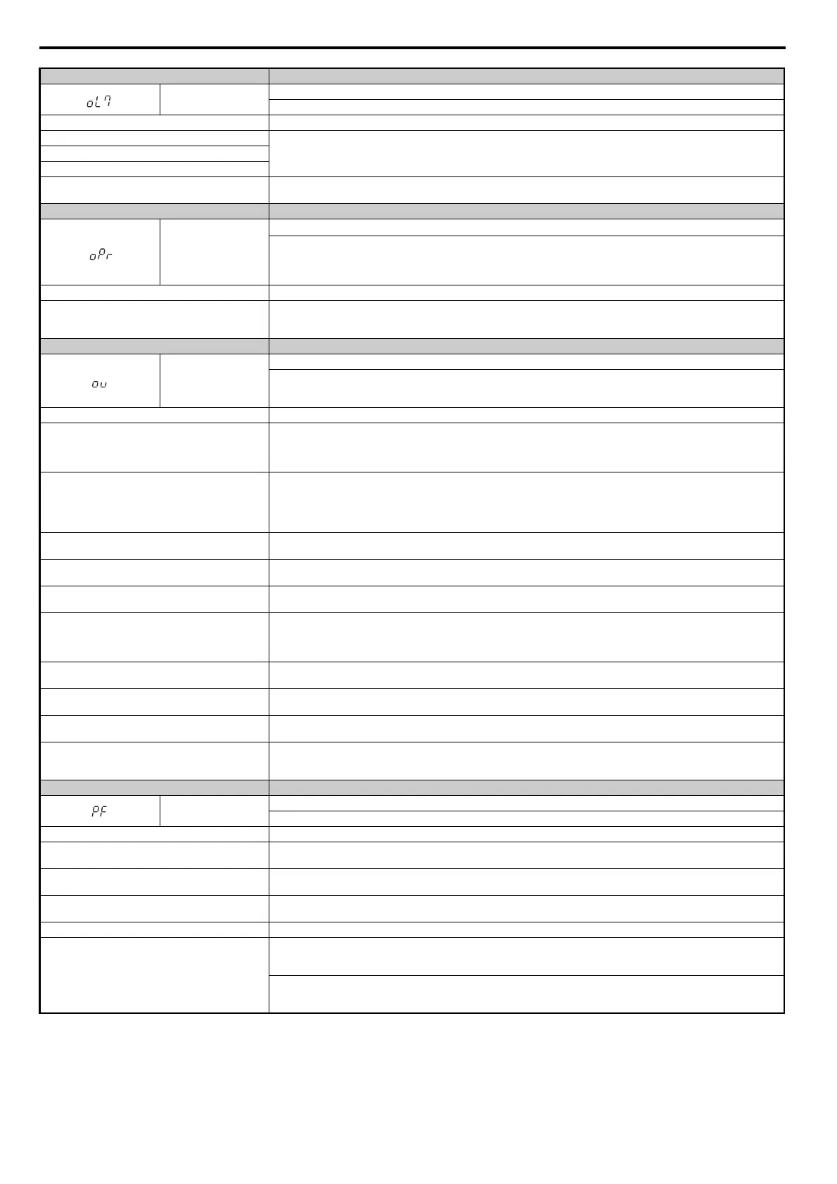
Digital Operator Display Fault Name
oL7
High Slip Braking oL
The output frequency stayed constant for longer than the time set in n3-04 during High Slip Braking.
Cause Possible Solution
Excessive load inertia.
• Reduce deceleration times in parameters C1-02, C1-04, for applications that do not use High Slip Braking.
• Use dynamic braking options to shorten deceleration time.
Motor is driven by the load.
Something on the load side is restricting deceleration.
The overload time during High Slip Braking is too short.
• Increase parameter n3-04 (High-slip Braking Overload Time).
• Install a thermal relay and increase the setting of n3-04 to the maximum value.
Digital Operator Display Fault Name
oPr
External Digital Operator Connection Fault
• The external operator has been disconnected from the drive.
Note: An oPr fault will occur when all of the following conditions are true:
• Output is interrupted when the operator is disconnected (o2-06 = 1).
• The Run command is assigned to the operator (b1-02 = 0 and LOCAL has been selected).
Cause Possible Solution
External operator is not properly connected to the drive.
• Check the connection between the operator and the drive.
• Replace the cable if damaged.
• Turn off the drive input power and disconnect the operator. Next reconnect the operator and turn the drive input power back on.
Digital Operator Display Fault Name
ov
Overvoltage
Voltage in the DC bus has exceeded the overvoltage detection level.
• For 200 V class: approximately 410 V
• For 400 V class: approximately 820 V
Cause Possible Solution
Deceleration time is too short and regenerative energy is
flowing from the motor into the drive.
• Increase the deceleration time (C1-02, C1-04).
• Install dynamic braking options.
• Enable stall prevention during deceleration (L3-04 = 1).
Stall Prevention is enabled as the default setting.
Fast acceleration time causes the motor to overshoot the
speed reference.
• Check if sudden drive acceleration triggers an overvoltage alarm.
• Increase the acceleration time.
• Use longer S-curve acceleration and deceleration times.
• Enable the Overvoltage Suppression function (L3-11 = 1).
• Lengthen the S-curve at acceleration end.
Excessive braking load.
The braking torque was too high, causing regenerative energy to charge the DC bus. Reduce the braking torque, use a dynamic
braking option, or lengthen decel time.
Surge voltage entering from the drive input power.
Install a DC reactor.
Note: Voltage surge can result from a thyristor convertor and phase advancing capacitor using the same input power supply.
Ground fault in the output circuit causing the DC bus
capacitor to overcharge.
• Check the motor wiring for ground faults.
• Correct grounding shorts and turn the power back on.
Improper Setting of Speed Search related parameters.
(Includes Speed Search after a momentary power loss
and after a fault restart.)
• Check the settings for Speed Search-related parameters.
• Enable Speed Search restart function (b3-19 greater than or equal to 1 to 10).
• Adjust the current level during Speed Search and the deceleration time (b3-02 and b3-03 respectively).
• Perform Stationary Auto-Tuning for line-to-line resistance and then enable Speed Estimation Speed Search (b3-24 = 1).
Drive input power voltage is too high.
• Check the voltage.
• Lower drive input power voltage within the limits listed in the specifications.
Drive fails to operate properly due to noise interference.
• Review the list of possible solutions provided for controlling noise.
• Review the section on handling noise interference and check the control circuit lines, main circuit lines, and ground wiring.
Load inertia has been set incorrectly.
• Check the load inertia settings when using KEB, overvoltage suppression, or Stall Prevention during deceleration.
• Adjust the load inertia ratio in L3-25 to better match the load.
Motor hunting occurs.
• Adjust the parameters that control hunting.
• Set the gain for Hunting Prevention (n1-02).
• Adjust the speed feedback detection suppression gain for PM motors (n8-45) and the time constant for pull-in current (n8-47).
Digital Operator Display Fault Name
PF
Input Phase Loss
Drive input power has an open phase or has a large imbalance of voltage between phases. Detected when L8-05 = 1 (enabled).
Cause Possible Solution
There is phase loss in the drive input power.
• Check for wiring errors in the main circuit drive input power.
• Correct the wiring.
There is loose wiring in the drive input power terminals.
• Ensure the terminals are tightened properly.
• Apply the tightening torque as specified in this manual. Refer to Wire Gauges and Tightening Torque on page 73
There is excessive fluctuation in the drive input power
voltage.
• Check the voltage from the drive input power.
• Review the possible solutions for stabilizing the drive input power.
There is poor balance between voltage phases. • Stabilize drive input power or disable phase loss detection.
The main circuit capacitors are worn.
• Check the maintenance time for the capacitors (U4-05).
• Replace the capacitor if U4-05 is greater than 90%. For instructions on replacing the capacitor, contact Yaskawa or your nearest
sales representative.
Check for anything problems with the drive input power. If drive input power appears normal but the alarm continues to occur,
replace either the control board or the entire drive. For instructions on replacing the control board, contact Yaskawa or your
nearest sales representative.
SIEP_C710616_35.book 272 ページ 2015年11月30日 月曜日 午後2時2分