6.4 Fault Detection
YASKAWA ELECTRIC SIEP C710616 35D YASKAWA AC Drive E1000 Technical Manual 273
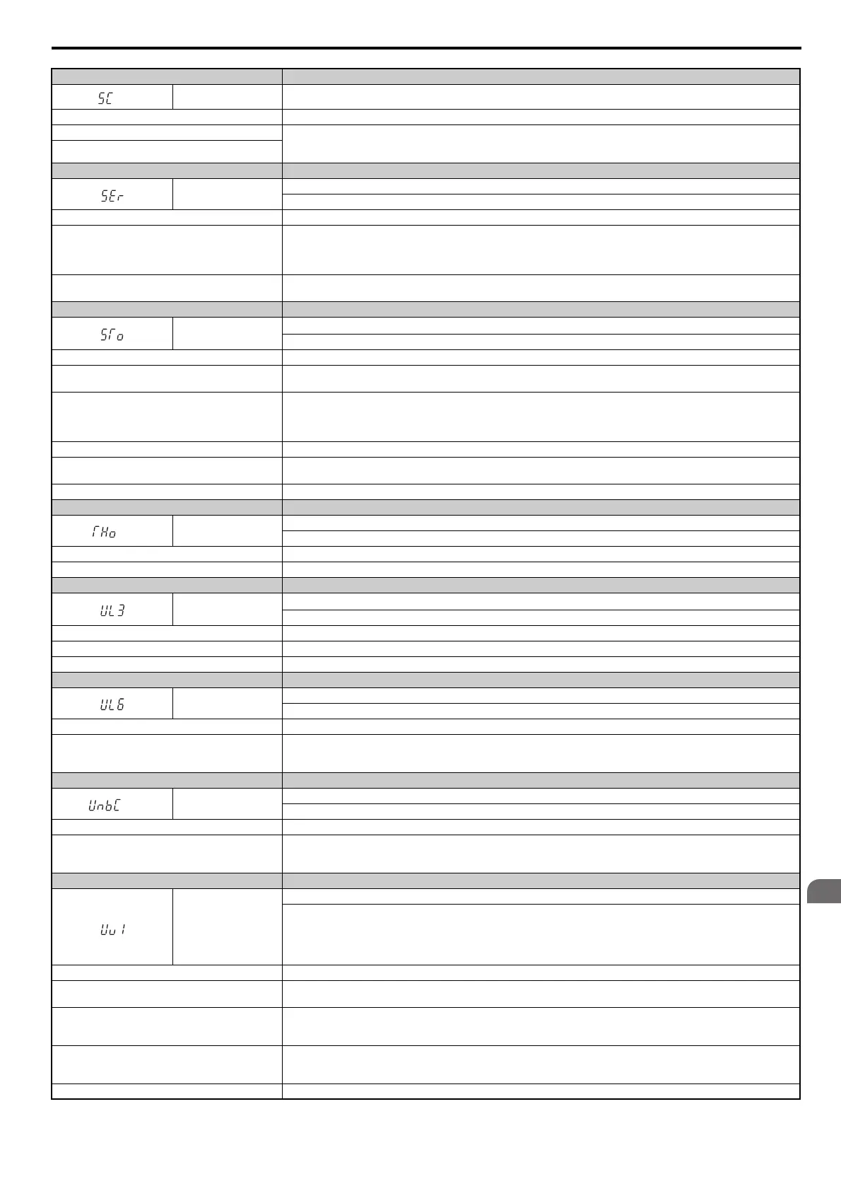
Digital Operator Display Fault Name
<3>
SC IGBT Short Circuit
Cause Possible Solution
IGBT fault. • Check the wiring to the motor.
• Turn the power supply off and then on again to check operation.
If the problem continues, contact your Yaskawa representative or nearest Yaskawa sales office.
IGBT short circuit detection circuit fault.
Digital Operator Display Fault Name
SEr
Too Many Speed Search Restarts
The number of Speed Search restarts exceeded the number set to b3-19.
Cause Possible Solution
Speed Search parameters are set to the wrong values.
• Reduce the detection compensation gain during Speed Search (b3-10).
• Increase the current level when attempting Speed Search (b3-17).
• Increase the detection time during Speed Search (b3-18).
• Repeat Auto-Tuning.
The motor is coasting in the opposite direction of the
Run command.
Enable Bi-Directional Speed Search (b3-14 = 1).
Digital Operator Display Fault Name
STo
Motor Pull Out or Step Out Detection
Motor pull out or step out has occurred. Motor has exceeded its pull-out torque.
Cause Possible Solution
The wrong motor code is set (Yaskawa motors only).
• Enter the correct motor code for the PM being used into E5-01.
• For special-purpose motors, enter the correct data to all E5 parameters according to the test report provided for the motor.
Load is too heavy.
• Increase the load inertia for PM motor (n8-55).
• Increase the pull-in current during accel/decel (n8-51).
• Reduce the load.
• Increase the motor or drive capacity.
Load inertia is too heavy. Increase the load inertia for PM motor (n8-55).
Acceleration and deceleration times are too short.
• Increase the acceleration and deceleration times (C1-01 through C1-04).
• Increase the S-curve acceleration and deceleration times (C2-01).
Speed response is too slow. Increase the load inertia for PM motor (n8-55).
Digital Operator Display Fault Name
<2>
THo
Thermistor Disconnect
The thermistor used to detect motor temperature has become disconnected.
Cause Possible Solution
The motor thermistor is not connected properly. Check the wiring for the thermistor.
Digital Operator Display Fault Name
UL3
Undertorque Detection 1
The current has fallen below the minimum value set for torque detection (L6-02) for longer than the allowable time (L6-03).
Cause Possible Solution
Parameter settings are not appropriate for the load. Check the settings of parameters L6-02 and L6-03.
There is a fault on the machine side. Check the load for any problems.
Digital Operator Display Fault Name
UL6
Motor Underload
The weight of the load has fallen below the underload curve defined in L6-14.
Cause Possible Solution
The output current has fallen below the motor underload
curve defined in L6-14 for longer than the time set to
L6-03.
Adjust the value set to L6-14 so that output current remains above the motor underload curve during normal operation.
Digital Operator Display Fault Name
<2>
UnbC
Current Unbalance
Current flow has become unbalanced.
Cause Possible Solution
The internal current sensor has detected a current
unbalance situation.
• Check wiring.
• Check for damaged transistors.
• Check for short circuits or grounding problems on the connected motor.
Digital Operator Display Fault Name
Uv1
DC Bus Undervoltage
One of the following conditions occurred while the drive was running:
• Voltage in the DC bus fell below the undervoltage detection level (L2-05)
• For 200 V class: approximately 190 V
• For 400 V class: approximately 380 V (350 V when E1-01 is less than 400) The fault is output only if L2-01 = 0 or L2-01 = 1
and the DC bus voltage has fallen below the level set to L2-05 for longer than the time set to L2-02.
Cause Possible Solution
Input power phase loss.
• The main circuit drive input power is wired incorrectly.
• Correct the wiring.
One of the drive input power wiring terminals is loose.
• Ensure there are no loose terminals.
• Apply the tightening torque specified in this manual to fasten the terminals. Refer to Wire Gauges and Tightening Torque on
page 73
There is a problem with the voltage from the drive input
power.
• Check the voltage.
• Correct the voltage to be within the range listed in drive input power specifications.
• If there is no problem with the power supply to the main circuit, check for problems with the main circuit magnetic contactor.
The power has been interrupted. Correct the drive input power.
SIEP_C710616_35.book 273 ページ 2015年11月30日 月曜日 午後2時2分